A Planar Decoupling Complicated Trajectory Polishing Equipment
A complex and polishing technology, applied in grinding/polishing equipment, metal processing equipment, other manufacturing equipment/tools, etc., can solve the problems of single running track, poor processing stability, easy aging of equipment, etc., and achieve decoupling of grinding state , Improved sharpening efficiency and good processing quality
- Summary
- Abstract
- Description
- Claims
- Application Information
AI Technical Summary
Problems solved by technology
Method used
Image
Examples
specific Embodiment approach 1
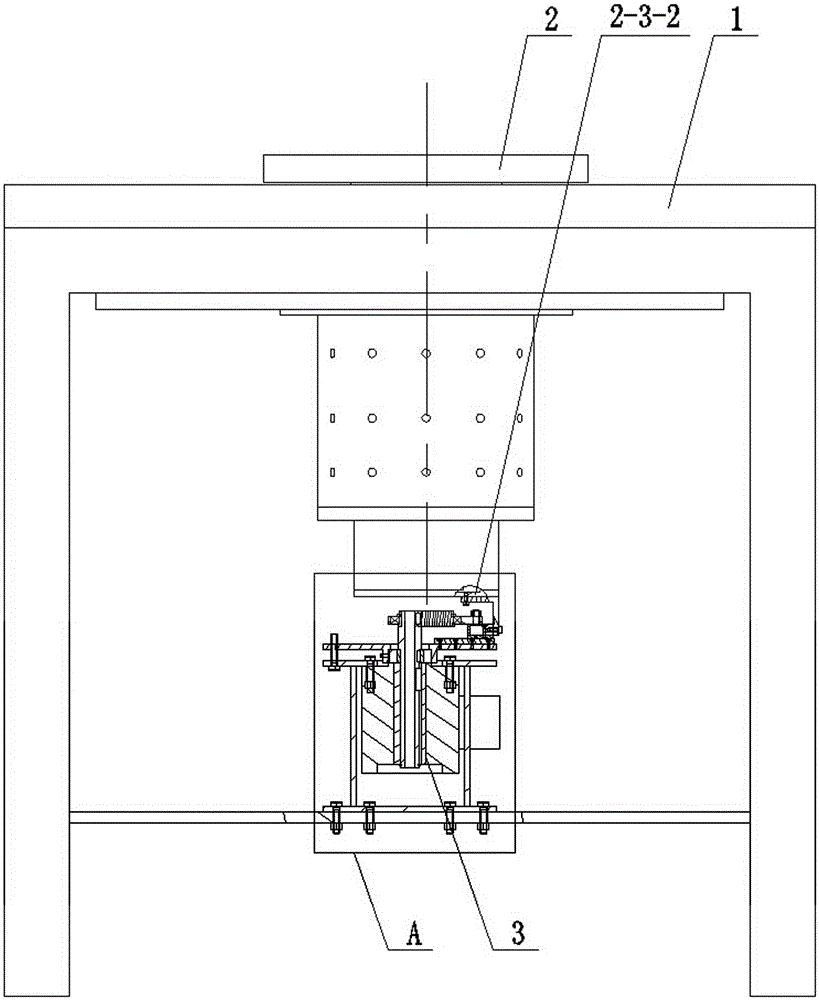
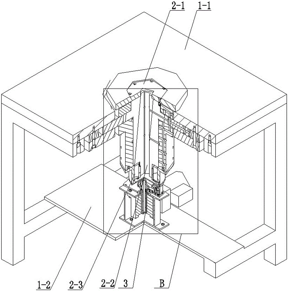
[0026] Specific implementation mode one: as Figure 1 to Figure 9 As shown, a plane decoupling complex trajectory polishing equipment includes a frame 1, an air bearing spindle shaft system 2 and a mechanism control part 3, and the mechanism control part 3 includes a motor support 3-1, a hollow right-angle motor 3 -2, central shaft 3-3, one-way bearing 3-4, turntable 3-5, connecting rod 3-6, deep groove ball bearing 3-7, eccentric wheel 3-8, needle bearing unit 3-9, transition Plate 3-10, linear guide pair 3-11, bent plate 3-12 and positioning bolt 3-13;
[0027] The top of the frame 1 is provided with a workbench 1-1, the bottom of the frame 1 is provided with a supporting plate 1-2, the center of the workbench 1-1 of the frame 1 is provided with a through hole, and the center of the workbench 1-1 is provided with a through hole. The air-floating spindle shaft system 2 is vertically installed in the hole (the workbench 1-1 is also used as the upper thrust plate of the air-fl...
specific Embodiment approach 2
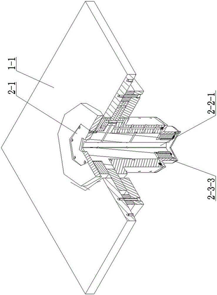
[0032] Specific implementation mode two: as Figure 1~Figure 9 As shown, the plane decoupling complex trajectory grinding and polishing equipment described in the first specific embodiment, the air-floating spindle shaft system 2 includes a polishing disc 2-1, an air-floating spindle component 2-2 and a frameless motor component 2 -3; the air-floating main shaft part 2-2 is vertically arranged, and the polishing disc 2-1 is horizontally arranged on the upper end of the air-floating main shaft part 2-2, and the two are detachably connected by screws; the air-floating main shaft part 2-2 The air bearing main shaft part 2-2 is driven by the frameless motor part 2-3 to realize high-precision rotary motion.
[0033] The air-floating spindle part 2-2 is composed of an inner ring air-floating system and an outer ring closed air-floating thrust system; the inner ring air-floating system adopts a T-shaped layout, and the inner ring air-floating system includes an air-floating spindle ...
PUM
| Property | Measurement | Unit |
|---|---|---|
| radius | aaaaa | aaaaa |
| surface roughness | aaaaa | aaaaa |
Abstract
Description
Claims
Application Information
 - R&D
- Intellectual Property
- Life Sciences
- Materials
- Tech Scout
- Unparalleled Data Quality
- Higher Quality Content
- 60% Fewer Hallucinations
Browse by: Latest US Patents, China's latest patents, Technical Efficacy Thesaurus, Application Domain, Technology Topic, Popular Technical Reports.
© 2025 PatSnap. All rights reserved.Legal|Privacy policy|Modern Slavery Act Transparency Statement|Sitemap|About US| Contact US: help@patsnap.com


