
A complex trajectory research and throwing equipment for natural diamond knife blade grinding

A diamond tool and equipment technology, applied in the field of precision and ultra-precision machining, can solve the problems of unsatisfactory machining stability, single running track, easy aging of equipment, etc., achieve system stability and good economic practicability, and improve sharpening quality. , the effect of convenient control

Active Publication Date: 2016-05-04
HARBIN INST OF TECH
View PDF6 Cites 0 Cited by
  • Summary
  • Abstract
  • Description
  • Claims
  • Application Information

AI Technical Summary

Problems solved by technology

[0010] The purpose of the present invention is to provide a complex track grinding and polishing equipment for natural diamond tool sharpening, so as to solve the problems that the current diamond tool sharpening equipment has a single running track, complicated control, easy aging of equipment, and unsatisfactory processing stability

Method used


Image

  • A complex trajectory research and throwing equipment for natural diamond knife blade grinding
  • A complex trajectory research and throwing equipment for natural diamond knife blade grinding
  • A complex trajectory research and throwing equipment for natural diamond knife blade grinding

Examples


specific Embodiment approach 1

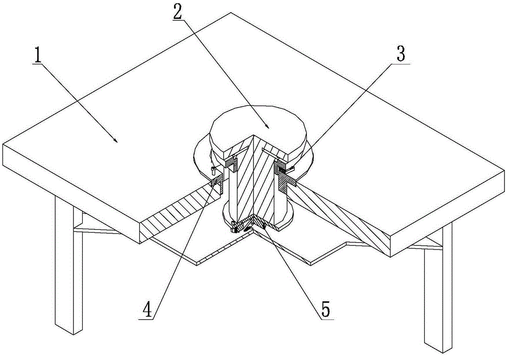
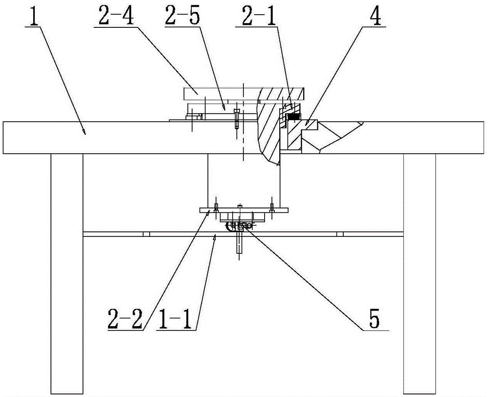
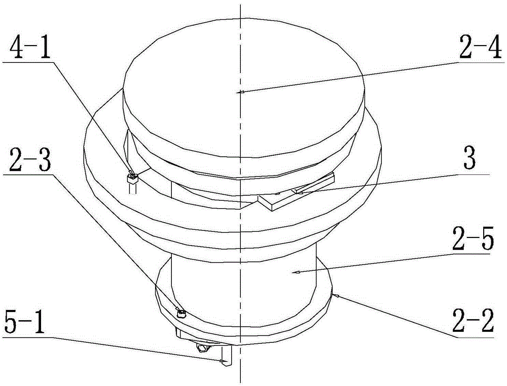
[0020] Specific implementation mode one: combine Figure 1-Figure 4Describe this embodiment. The equipment in this embodiment includes a bed 1, an air-floating spindle shaft system 2, a precision guide rail pair 3, a thrust air-bearing bearing 4, and a mechanism control component 5. The air-floating spindle shaft system 2 includes The supporting plate 2-1, the main shaft lower supporting plate 2-2, the first positioning locking screw 2-3 and the main shaft 2-5, the mechanism control part 5 includes the drive shaft 5-1, the self-aligning screw 5-2, Locking support 5-3, connecting rod 5-4 and eccentric wheel 5-5;

[0021] A thrust air bearing 4 is installed on the bed 1, an air bearing spindle shaft system 2 is installed inside the thrust air bearing 4, an upper spindle supporting plate 2-1 is installed on the upper part of the spindle 2-5, and a spindle upper supporting plate 2 -1 is installed together with the thrust air bearing 4 through the precision guide rail pair 3, and ...

specific Embodiment approach 2

[0023] Specific implementation mode two: combination figure 1 To illustrate this embodiment, the equipment of this embodiment further includes a grinding and polishing disc 2-4, and the top end of the main shaft 2-5 is installed with the grinding and polishing disc 2-4. Other implementation manners are the same as the specific implementation manner 1.

[0024] Working principle: When the first positioning locking screw 2-3 fixes the eccentric wheel 5-5 and the connecting rod 5-4 as one and the second positioning locking screw 4-1 is loosened, due to the drive shaft 5-1 and the installation The thrust air bearing 4 with the precision guide rail pair 3 has a certain amount of eccentricity. Through the coupling of the linear motion of the precision guide rail pair 3 and the circular motion of the thrust air bearing 4, a rotary guide rod mechanism is formed to realize air bearing The main shaft shaft system 2 is in the compound motion form of sinusoidal and circular superimpositi...


PUM

PropertyMeasurementUnit
radiusaaaaaaaaaa

Abstract

The invention provides complex-track polishing equipment used for natural diamond cutting tool grinding, and relates to the technical field of precision and ultra-precision machining. The equipment solves the problems that existing diamond cutting tool grinding equipment is single in moving track, complex in control, prone to aging and not ideal in machining stability. A thrust gas bearing is installed on a machine body, a gas spindle shafting is installed in the thrust gas bearing, an upper spindle supporting plate is installed on the upper portion of a spindle, the upper spindle supporting plate and the thrust gas bearing are installed together through a precise track pair, and the thrust gas bearing is provided with a second positioning locking screw. An eccentric wheel is rotating connection with a connecting rod, a locking support is fixedly installed at the bottom of the eccentric wheel, a self-aligning lead screw is installed on the locking support, a driving shaft is in threaded connection with the self-aligning lead screw, the driving shaft makes contact with the eccentric wheel by using a guide groove, and a first locking screw enables a lower spindle supporting plate, the eccentric wheel and the connecting rod to be connected together. The complex-track polishing equipment is used for complex-track polishing machining of a natural diamond cutting tool.

Description

technical field [0001] The invention relates to the technical field of precision and ultra-precision machining, and more specifically relates to a complex trajectory lapping and polishing equipment used for sharpening natural diamond tools. Background technique [0002] Precision and ultra-precision machining technology is one of the most important parts of machinery manufacturing, because precision and ultra-precision machining technology not only directly affects the development of cutting-edge technology and defense industry, but also affects the precision and surface of civil mechanical products Quality affects the international competitiveness of products. In recent years, various new technologies, such as microelectronics technology, computer technology, automatic control technology, laser technology, etc., have been widely used in precision machining, making precision and ultra-precision machining technology develop by leaps and bounds, greatly improving its technolog...

Claims


Application Information

Patent Timeline
Patent Type & Authority Patents(China)
IPC IPC(8): B24B3/60
CPCB24B3/60
Inventor 宗文俊李增强曹志民孙涛
Owner HARBIN INST OF TECH
Learn More