Mining intrinsically-safe seismic source explosion excitation and synchronous triggering device used for coal mine underground seismic prospecting method

An intrinsically safe, seismic exploration technology, applied in the field of mine geophysical exploration, to achieve the effect of ingenious design, avoiding regular maintenance, and safe and reliable work

CN104155686AInactive Publication Date: 2014-11-19XIAN RES INST OF CHINA COAL TECH& ENG GROUP CORP
1 Cites 3 Cited by

Patent Information

Authority / Receiving Office
CN · China
Patent Type
Applications(China)
Current Assignee / Owner
Publication Date
2014-11-19
Estimated Expiration
Not applicable · inactive patent

Smart Images

  • Figure 1
    Figure 1
  • Figure 2
    Figure 2
  • Figure 3
    Figure 3
Patent Text Reader

Abstract

The invention particularly relates to a mining intrinsically-safe seismic source explosion excitation and synchronous triggering device used for a coal mine underground seismic prospecting method, and aims to solve a difficult problem how to meet national security requirements and extract TB synchronous triggering signals at the explosive moment. The device comprises a housing; an impulse current mutual inductor comprises a magnet ring shaft sleeve, a magnet ring, a coil and a blasting bus-bar; the magnet ring is embedded on the outer side of the magnet ring shaft sleeve; the head end and the tail end of the coil are used as outlet wire ends; wire passing holes are formed in the two end surfaces of the magnet ring shaft sleeve; a printed circuit block assembled with a pulse shaping circuit and a double-protection circuit is arranged inside the housing, and a waterproof joint for penetrating a TB signal cable and an indicating lamp are arranged inside the housing; one end of the TB signal cable is connected with the double-protection circuit, and a connector plug is arranged at the other end of the TB signal cable. According to the invention, the feedthrough impulse current and mutual induction isolation technology and the pulse shaping double protection intrinsically-safe 'ib' explosion-proof technology are adopted, and a problem that the use of an electric-associated manner is limited, is solved.
Need to check novelty before this filing date? Find Prior Art

Description

technical field

[0001] The invention belongs to the technical field of mine geophysical exploration, and in particular relates to a mining intrinsically safe seismic source detonation synchronous triggering device suitable for underground seismic exploration methods in coal mines. Background technique

[0002] The basic principle of the mine seismic exploration method is the same as that of the surface seismic exploration, and explosives are usually used as the "shock source" to excite seismic waves. In order to ensure that the seismic instrument can start data acquisition in time and accurately from the moment the source is excited, a detonation synchronous trigger device must be equipped between the source and the seismic instrument. Its working process is that when the "blasting" command is issued, at the moment when the detonator generates a high-voltage pulse to detonate the explosive, the synchronous trigger device for detonating the seismic source converts the pulse c...

Examples

Embodiment Construction

[0029] A detailed description will be given below in conjunction with the drawings and the embodiments of the present invention:

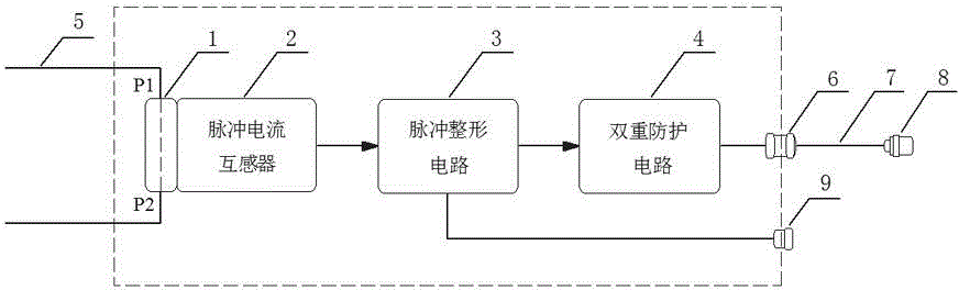
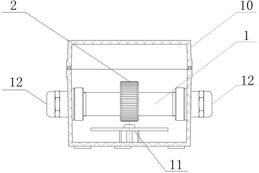
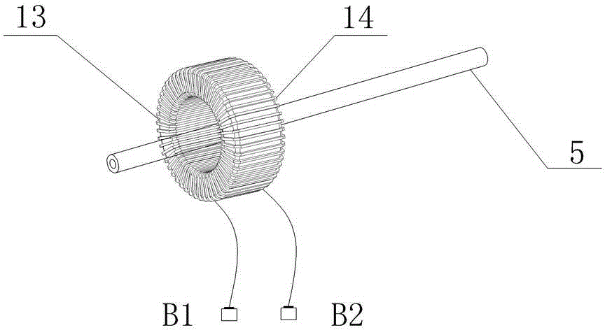
[0030] See figure 1 — Figure 4 , The present invention is an intrinsically safe seismic source blasting synchronization trigger device used in mine seismic exploration. It includes an organic shell 10, a magnetic ring sleeve 1 fixed inside the housing 10, and a supply on the magnetic ring sleeve 1. The blast bus 5 penetrates through the wire hole 12, and a circular magnetic ring 13 wound with the secondary coil 14 is arranged inside the casing 10. The secondary coil 14 wound on the magnetic ring 13 forms the head end B1 and the tail end B2 For the outlet terminal of the pulse current transformer 2, the magnetic ring 13 is embedded and fixed on the magnetic ring sleeve 1, and two end faces of the magnetic ring sleeve 1 are provided with wire holes 12 and located outside the casing 10; A printed circuit board 11 is provided inside the housing 10, and t...