Adjusting a hand under a dial

A dial and indicator technology, which is applied to visually indicate time, clocks, mechanically driven clocks, etc., can solve the problem of detracting from the attractiveness of clocks

Active Publication Date: 2014-11-19
ETA SA MFG HORLOGERE SUISSE
View PDF11 Cites 4 Cited by
  • Summary
  • Abstract
  • Description
  • Claims
  • Application Information

AI Technical Summary

Problems solved by technology

The versatility therefore necessitates that the dial has as many apertures as there are options for positioning the small seconds arbor, or other current time display functions, or timing functions, or other functions, which detracts from the appeal of the timepiece

Method used


Image

  • Adjusting a hand under a dial
  • Adjusting a hand under a dial
  • Adjusting a hand under a dial

Examples


Embodiment Construction

[0031] The present invention relates to the field of timepieces and more particularly to the field of visual display mechanisms.

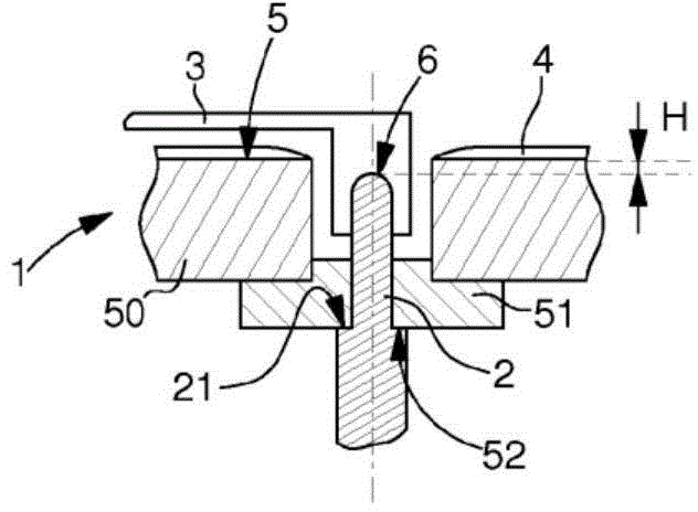
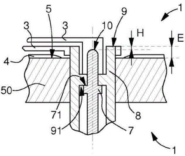
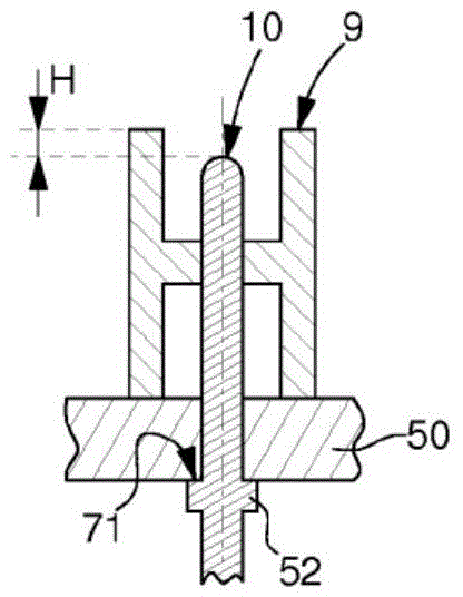
[0032] More specifically, the present description and drawings show a preferred, non-limiting example of a display realized by hands, for which the invention proposes to fit the hands under the dial.

[0033] The invention relates to a timepiece movement 1 driving at least one output arbor 2 or 7 intended to receive an indicator 3 displaying a physical or time quantity, facing at least one complementary indicator or Dial 4 and above it. Said complementary indicator or dial 4 is arranged at the position of a local reference surface or bearing surface 5 of a structure 50, such as a main board or a splint, etc., said local reference surface or bearing surface 5 surrounding the movement 1 Each output arbor 2 or 7 in the movement 1 is partially contained in the movement 1 ; alternatively, said complementary indicator or dial 4 is arranged on a local re...


PUM


Abstract

The invention relates to a timepiece movement (1) driving at least one output arbor (2, 7) for receiving an indicator (3), for displaying a physical quantity or a quantity of time, opposite and above at least one complementary indicator or a dial (4), said complementary indicator or dial (4) being arranged at a local reference or bearing surface (5) that said movement (1) locally comprises, around (each of) said output arbor(s) (2, 7) of said movement (1), or being arranged on said local reference or bearing surface (5). Said at least one output arbor (2) comprises, on the side of said local reference or bearing surface (5) thereof, a free end (6) that is either set back from or just flush with said local reference or bearing surface (5) thereof.

Description

technical field [0001] The invention relates to a timepiece movement driving at least one output arbor for receiving an indicator displaying a physical or time quantity and facing and above at least one complementary indicator or dial, Said at least one complementary indicator or dial is arranged at or on a local reference or bearing surface partly contained in said movement, said at least one output arbor comprised in The free end on one side of the local reference plane or bearing surface, the free end is concave or flush with respect to the local reference plane or bearing surface. [0002] The invention also relates to a modular timepiece assembly comprising at least one timepiece movement as described above. [0003] The invention also relates to a timepiece formed from a modular assembly of the type described above. [0004] The present invention relates to the field of timepieces and more particularly to the field of visual display mechanisms. Background technique ...

Claims


Application Information

Patent Timeline
Patent Type & Authority Applications(China)
IPC IPC(8): G04B19/02G04B19/04
CPCG04B19/02G04B19/044G04B19/06
Inventor B·怀斯博得
Owner ETA SA MFG HORLOGERE SUISSE
Why Eureka
Try Eureka