finger skateboard
A skateboard and finger technology, applied in the field of electric remote control toy finger skateboards, can solve the problems of electric toys having no entertainment value, single finger skateboard play, easy to slip, etc., to increase electric entertainment time, increase sports fun, and save electricity. Effect
- Summary
- Abstract
- Description
- Claims
- Application Information
AI Technical Summary
Problems solved by technology
Method used
Image
Examples
Embodiment approach 1
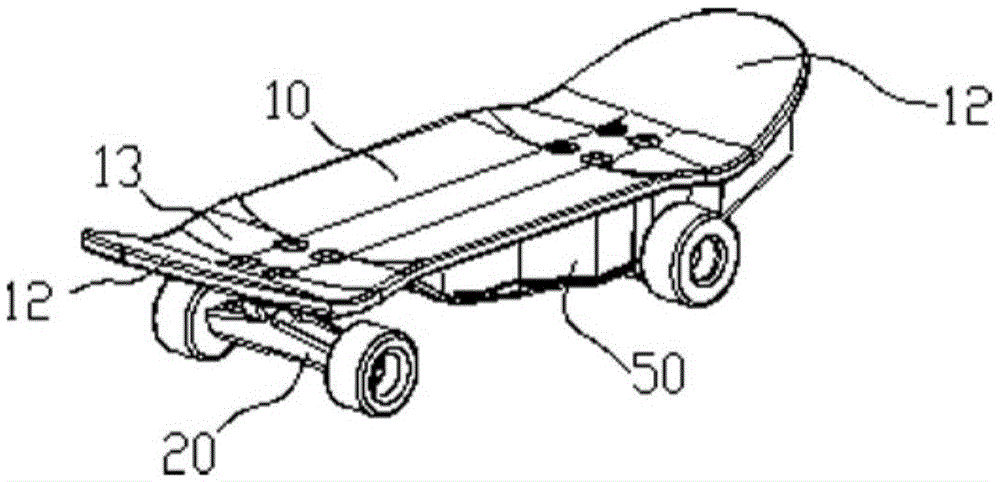
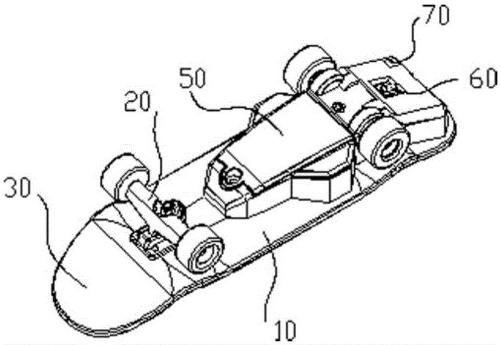
[0026] Such as Figure 1 to Figure 7 As shown, the finger skateboard includes a board body 10 and a pulley block 20. The board body 10 includes a middle board 11 and two end boards 12. The two end boards 12 are respectively connected to the two ends of the middle board 11. The two ends of the middle board 11 are provided with In the anti-slip groove 13, the pulley block 20 is arranged at the bottom of the plate body. see details image 3 shown. In order to conform to ergonomics and prevent fingers from falling off the slide plate, the cross-sectional shape of the groove 13 is arc-shaped, which is consistent with the radian of the cross-sectional shape of the finger contact surface. For details, see Figure 4 shown. The quantity of described pulley group 20 is two, and they are respectively arranged on the two ends of plate body 10 bottoms, described pulley group 20 comprises pulley 21, support 22 and fixed seat 23, and described support 22 is provided with rotating shaft 25...
Embodiment approach 2
[0030] Such as Figure 1 to Figure 7 The shown finger skateboard includes a board body 10, a pulley block 20 and a driving device 50. The board body 11 includes a middle board 11 and two end boards 12, and the two end boards 12 are respectively connected to the two ends of the middle board 11, and the two ends of the middle board 11 are The end is provided with a groove 13 for anti-slip, the driving device 50 is arranged on the bottom of the plate body 10, the pulley block 20 is arranged in the driving device 50, and the driving device 50 includes a casing 51, a driving power supply 52, a switch 60, Wireless signal receiver 70, driving motor 53, steering gear 55, speed change gear 56, transmission gear 57 and rotating shaft 58, specifically see Image 6 ,; the drive motor 53, the switch 60, the wireless signal receiver 70 are electrically connected to the drive power supply 52, the steering gear 55 is arranged at the output end of the drive motor 53, and the speed change gear ...
PUM
 Abstract
Description
Claims
Application Information
 - R&D
- Intellectual Property
- Life Sciences
- Materials
- Tech Scout
- Unparalleled Data Quality
- Higher Quality Content
- 60% Fewer Hallucinations
Browse by: Latest US Patents, China's latest patents, Technical Efficacy Thesaurus, Application Domain, Technology Topic, Popular Technical Reports.
© 2025 PatSnap. All rights reserved.Legal|Privacy policy|Modern Slavery Act Transparency Statement|Sitemap|About US| Contact US: help@patsnap.com


