Method and device for spectrum allocation in spectral flexible optical network

A spectrum allocation and optical network technology, applied in the field of spectrum flexible optical network, can solve problems such as blocked connection requests and inability to allocate large enough spectrum blocks, and achieve the effect of reducing blocking rate and spectrum fragmentation

Active Publication Date: 2014-12-10
BEIJING UNIV OF POSTS & TELECOMM
3 Cites 5 Cited by

AI-Extracted Technical Summary

Problems solved by technology

The existence of these spectrum fragments makes the network unable to allocate a large en...

Abstract

The invention discloses a method and a device for spectrum allocation in a spectral flexible optical network and relates to the technical field of the spectral flexible optical networks. According to the method and the device for spectrum allocation in the spectral flexible optical network, operations, topologies and spectral gaps all classified, and then the spectral gaps are selected by use of the corresponding topologies according to the types of the operations; as a result, the regularization of spectrum occupation is realized, spectrum fragments are reduced and the congestion probability is reduced.

Application Domain

Multiplex system selection arrangementsData switching networks

Technology Topic

Computer scienceFrequency spectrum +1

Image

  • Method and device for spectrum allocation in spectral flexible optical network
  • Method and device for spectrum allocation in spectral flexible optical network
  • Method and device for spectrum allocation in spectral flexible optical network

Examples

  • Experimental program(1)

Example Embodiment

[0053] Example
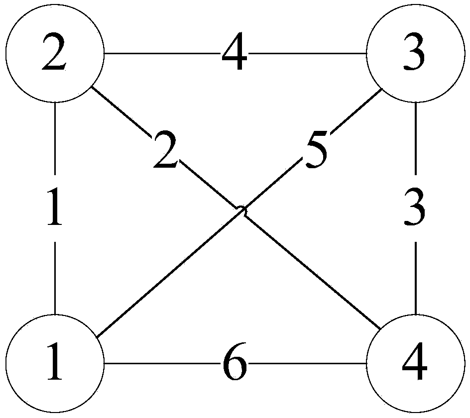
[0054] A specific embodiment is used below to illustrate the present invention, but does not limit the protection scope of the present invention. This embodiment implements spectrum allocation through a two-dimensional spectrum space. As shown in Figure 2(a), a spectrum-flexible optical network includes 4 optical nodes, and 4 optical nodes are interconnected by 6 links.
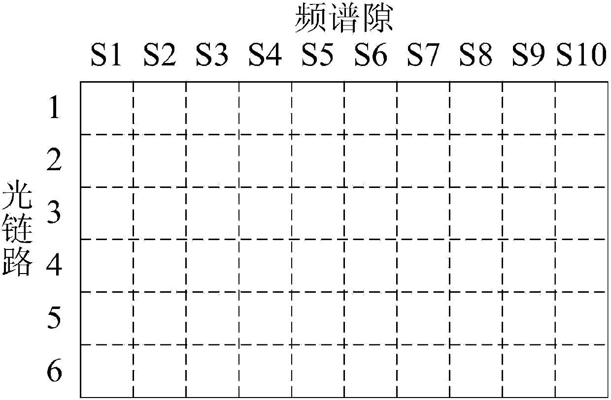
[0055] The two-dimensional spectrum space refers to the two-dimensional spectrum resource space formed by the link space (first dimension) and the spectrum gap space (second dimension) in the spectrum flexible optical network. Because the spectrum slot width and spectrum range of any link are the same, if the spectrum resources of the entire network are expressed in units of spectrum slots, it can be expressed as a two-dimensional spectrum space, as shown in Figure 2(b). Assume that there are 4 types of services in a spectrum-flexible optical network, namely 10Gb/s, 40Gb/s, 100Gb/s and 400Gb/s. The required spectrum bandwidth corresponds to 25GHz, 50GHz, 50GHz, 75GHz, and the required number of spectrum slots are respectively Is {1, 2, 2, 3}.
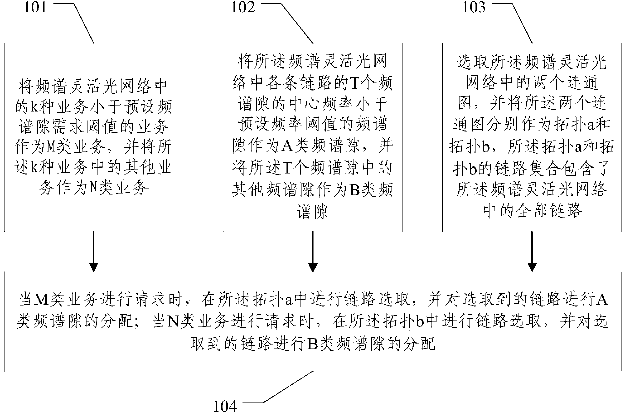
[0056] The method of this embodiment specifically includes:
[0057] Step 1: Business classification. Set the preset spectrum slot demand threshold|B n |=2.5(2 n | <3), respectively divide the services whose number of spectrum slot requirements are less than and greater than this threshold into two categories: Class M (including 1, 2) and Class N (including 3).
[0058] Step 2: Divide the two-dimensional spectrum space. This step specifically includes steps 2.1 and 2.2:
[0059] Step 2.1: Spectral gap space classification. Suppose the number of spectrum slots in each link in the spectrum-flexible optical network is 10, and the spectrum slots with the center frequency from small to large are S1, S2, S3...S10. Set the preset frequency threshold to w n (S4 n image 3 Shown.
[0060] Step 2.2: Link space classification. Select two connected graphs in the spectrum flexible optical network, and use the two connected graphs as topology a and topology b, respectively, and the link set of topology a and topology b includes the spectrum flexible optical network Refer to Figure 4(a) for the topology a, and Figure 4(b) for the topology b. The links contained in topology a are regarded as type a, and the links contained in topology b are regarded as type b, as shown in Figure 4(c). At this time, the entire two-dimensional spectrum space forms four categories: Aa, Bb, Ab, Ba, as shown in Figure 4(d).
[0061] Step 3: Spectrum slot allocation. Perform path selection and spectrum resource allocation for different types of services. Take the following services 1, 2 as an example:
[0062] Business 1: Number of required spectrum slots slots = 2; optical node 1 → optical node 4;
[0063] At this time, since the number of spectrum slot requirements of service 1 is 2, it can be determined that it is an M service. Referring to Figure 5(a), the path of optical node 1 → optical node 4 can be determined by link selection from topology a The selected Type A links are 1 and 2. At this time, S1 and S2 are allocated from Type A spectrum slots (including S1, S2, S3, S4) as the spectrum slots allocated by Service 1 from Type Aa, refer to the figure 5(b);
[0064] Business 2: Number of required spectrum slots slots = 3; optical node 4 → optical node 1;
[0065] At this time, since the number of spectrum slot requirements for service 2 is 3, it can be determined to be N service. Referring to Figure 5(c), the path of optical node 4 → optical node 1 can be determined by link selection from topology b The selected link is 6. At this time, S8, S9, and S10 are allocated from the type B spectrum slots (including S5, S6, S7, S8, S9, S10) as the spectrum slots allocated by service 2 from the type Bb. Refer to Figure 5(d).
[0066] Step 4: Road construction and road demolition. After the spectrum slots of service 1 and service 2 are successfully allocated, the link will be constructed according to the selected link, and the transmission of service 1 and service 2 will be carried out according to the allocated spectrum slot. After the transmission of service 1 and service 2 is completed, the route will be disconnected , And release the allocated spectrum slot.
[0067] In order to facilitate the comparison between the spectrum allocation method in the prior art (the first adaptive spectrum resource allocation method) and the spectrum allocation method of this embodiment, the following compares the spectrum resource allocation status of 10 services, according to Figure 6(a ) And Figure 6(b), it can be seen that the spectrum occupancy of the spectrum allocation method of this embodiment is significantly more regular, and spectrum fragmentation is reduced, and the blocking rate is reduced.
[0068] Among them, suppose these 10 businesses are:
[0069] Business 1: slots=2; terminal 1→terminal 4 business 2: slots=3; terminal 4→terminal 1
[0070] Business 3: slots=3; terminal 1→terminal 4 business 4: slots=3; terminal 1→terminal 3
[0071] Business 5: slots = 3; terminal 3 → terminal 2 Business 6: slots = 1; terminal 3 → terminal 4
[0072] Service 7: slots=2; terminal 4→terminal 3 service 8: slots=3; terminal 1→terminal 2
[0073] Service 9: slots=1; terminal 2→terminal 1 service 10: slots=1; terminal 3→terminal 4
[0074] The invention also discloses a spectrum allocation device in a spectrum flexible optical network, with reference to Figure 7 , The device includes:
[0075] The service division module is used for taking k types of services in the spectrum flexible optical network whose services are less than the preset spectrum slot demand threshold as M types of services, and taking other services of the k types of services as N types of services, where k is An integer not less than 2;
[0076] The spectrum slot division module is configured to use the spectrum slots whose center frequencies of the T spectrum slots of each link in the spectrum flexible optical network are less than a preset frequency threshold as a type A spectrum slot, and divide the T spectrum slots into The other spectrum slots of are regarded as type B spectrum slots, and the T is an integer not less than 2;
[0077] The topology division module is used to select two connected graphs in the spectrum flexible optical network, and use the two connected graphs as topology a and topology b, respectively. The link set of topology a and topology b includes all All the links in the flexible spectrum optical network;
[0078] The service allocation module is used to select the link in the topology a when the M type of service is requested, and allocate the type A spectrum slot to the selected link; when the N type of service is requested, In the topology b, link selection is performed, and type B spectrum slot allocation is performed on the selected link.
[0079] Preferably, in the service allocation module, if the M type of service is not successfully allocated, then the selected link is allocated to the type B spectrum slot; if the allocation is still not successful, the link is selected in the topology b, and The selected link is allocated for type A spectrum slots. If the allocation is not successful, the selected link is allocated for type B spectrum slot; if the N service is not allocated successfully, the selected link is allocated for type A spectrum Slot allocation; if the allocation is still not successful, link selection is performed in the topology a, and the selected link is allocated for type B spectrum slots. If the allocation is not successful, the selected link is allocated for type A Allocation of spectrum slots.
[0080] Preferably, in the service allocation module, after the spectrum slot corresponding to the service is successfully allocated, the link is constructed according to the selected link, and the service is transmitted according to the allocated spectrum slot. After the service transmission is completed, the route is split, and Release the allocated spectrum slot.
[0081] Preferably, in the service distribution module, if a service request is not successfully distributed at the end, the service is blocked.
[0082] Preferably, each link in the spectrum flexible optical network has a weight;
[0083] When the service distribution module selects the link, it selects the link of the shortest path according to the weight of each link.

PUM

no PUM

Description & Claims & Application Information

We can also present the details of the Description, Claims and Application information to help users get a comprehensive understanding of the technical details of the patent, such as background art, summary of invention, brief description of drawings, description of embodiments, and other original content. On the other hand, users can also determine the specific scope of protection of the technology through the list of claims; as well as understand the changes in the life cycle of the technology with the presentation of the patent timeline. Login to view more.

Similar technology patents

Optimum path selection method of communication network based on load balance

InactiveCN101494590AReduce blocking rateoverall load balancing
Owner:ZTE CORP

Multicast traffic grooming method based on physical topology light-tree correction

ActiveCN104486094AReduce the waste of wavelength resourcesReduce blocking rate
Owner:XIDIAN UNIV

Enhancement type load balancing method based on adjacent region load information

InactiveCN102938910AReduce call drop rateReduce blocking rate
Owner:XIDIAN UNIV

Routing and spectrum allocation method based on path idleness in EON

ActiveCN112995805AReduce blocking rateImprove spectrum resource utilization
Owner:NANJING UNIV OF POSTS & TELECOMM

Classification and recommendation of technical efficacy words

  • Reduce blocking rate

Optimum path selection method of communication network based on load balance

InactiveCN101494590AReduce blocking rateoverall load balancing
Owner:ZTE CORP

Enhancement type load balancing method based on adjacent region load information

InactiveCN102938910AReduce call drop rateReduce blocking rate
Owner:XIDIAN UNIV

Multicast traffic grooming method based on physical topology light-tree correction

ActiveCN104486094AReduce the waste of wavelength resourcesReduce blocking rate
Owner:XIDIAN UNIV

Routing and spectrum allocation method based on path idleness in EON

ActiveCN112995805AReduce blocking rateImprove spectrum resource utilization
Owner:NANJING UNIV OF POSTS & TELECOMM
Why Eureka
Try Eureka