Supercharge Your Innovation With Domain-Expert AI Agents!

Tire inflation system having a sleeve shaped air passage

一种充气系统、轮胎的技术,应用在轮胎测量、轮胎零部件、车轮等方向,能够解决转动密封大等问题

Inactive Publication Date: 2014-12-24
DANA HEAVY VEHICLE SYSTEMS GROUP LLC
View PDF6 Cites 2 Cited by
  • Summary
  • Abstract
  • Description
  • Claims
  • Application Information

AI Technical Summary

Problems solved by technology

Alternatively, the rotary seal can become unnecessarily large when the path of the channel can be outside the axlebox

Method used


Image

  • Tire inflation system having a sleeve shaped air passage

Examples


Embodiment Construction

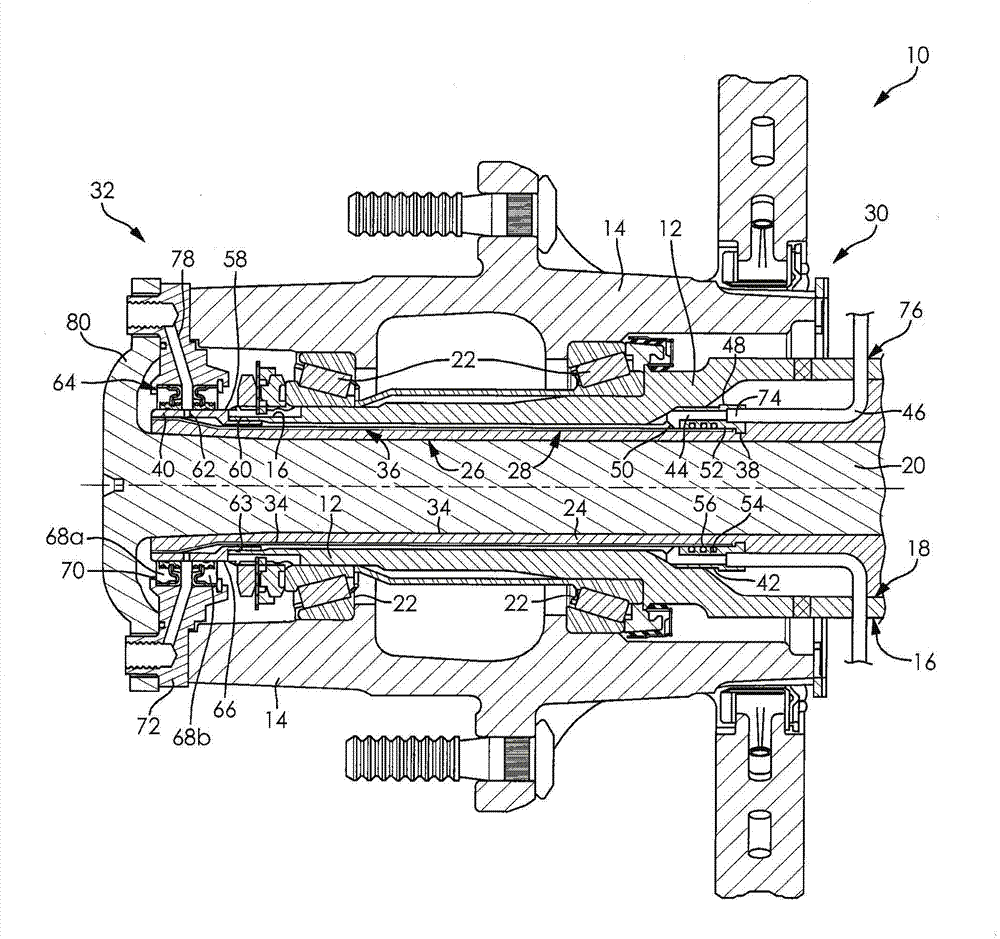
[0012] It should be understood that the invention may assume various alternative directions and sequences of steps, except where expressly specified to the contrary. It is also to be understood that the specific devices and processes shown in the drawings and described in the following description are simply exemplary embodiments of the inventive concepts defined in the appended claims. Therefore, no limitations are to be understood with respect to specific dimensions, orientations or other physical characteristics of the disclosed embodiments, unless expressly stated by the claims.

[0013] figure 1 A tire inflation system 10 is shown mounted to an axle spindle 12 and hub assembly 14 in accordance with an embodiment of the present invention. The axle journal 12 includes a radially outer surface 16 , a radially inner surface 18 . The axle journal 12 is a hollow member through which the axle shaft 20 is rotatably disposed. The axle spindle 12 may be integrally formed from an...


PUM


Abstract

A tire inflation system for a vehicle includes an axle spindle (12) having a radially outer surface and a radially inner surface, a sleeve (24) having a radially inner surface, a radially outer surface, an inboard end portion and an outboard end portion with a flared end. A cavity (36) is located between the radially inner surface of the axle spindle and the radially outer surface of the sleeve. The cavity being in fluid communication on an inboard end portion with a first rotary seal (38) and in communication on an outboard end portion with a second rotary seal (40), wherein the flared end of the sleeve closes the cavity on the outboard end portion.

Description

[0001] related application [0002] This application claims the benefit of US Provisional Application No. 61 / 605,881, filed March 2, 2012, which is hereby incorporated by reference in its entirety. field of invention [0003] The present invention relates to an improved structure for a tire inflation system used in a vehicle. Background of the invention [0004] This invention relates to inflation systems for vehicles, and more particularly, to tire inflation systems that use the cavity between the axle journal and the axle as a passage for a pressurized fluid, such as air. [0005] Tire inflation systems for vehicles are well known and are used to provide vehicles with versatility in different types of terrain or to reduce maintenance requirements. For example, the pressure of a plurality of tires in fluid communication with the tire inflation system may be reduced to provide additional traction to the vehicle and increased to reduce the rolling resistance of the vehicle. ...

Claims


Application Information

Patent Timeline
Patent Type & Authority Applications(China)
IPC IPC(8): B60C23/00
CPCB60C23/00336B60C23/00345B60C23/00363B60C23/00318B60B35/00
Inventor B·V·纳普克L·G·瑞茨纳
Owner DANA HEAVY VEHICLE SYSTEMS GROUP LLC
Features
  • R&D
  • Intellectual Property
  • Life Sciences
  • Materials
  • Tech Scout
  • Unparalleled Data Quality
  • Higher Quality Content
  • 60% Fewer Hallucinations
Learn More