

A control system for electric discharge machining
A control system and electric spark technology, applied in electric processing equipment, metal processing equipment, circuits, etc., can solve the problems of prolonged production process, cumbersome process, and increased cost.
- Summary
- Abstract
- Description
- Claims
- Application Information
AI Technical Summary
Problems solved by technology
Method used
Image

Examples
Embodiment Construction
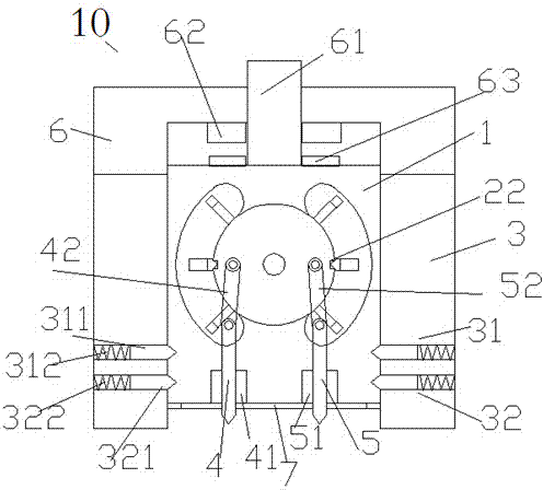
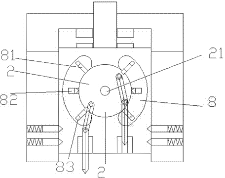
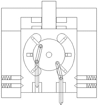
[0028] Refer below Figure 1-5 , describe the present invention in detail.
[0029] An electric discharge machining control system, which includes a controller and an electric discharge machining head device 10, the electric discharge machining head device 10 includes a lower frame 3, an upper frame 6 and an inner frame 1, and the upper frame 6 is in the Above the lower frame 3, the inner frame 1 is located in the chamber formed by the lower frame 3 and the upper frame 6, and can slide up and down;
[0030] Wherein, the upper inner side of the upper frame 6 and the upper side of the inner frame 1 are respectively provided with coupled electromagnetic coils 62 and magnets 63 to drive the sliding of the inner frame 1; The lower part of the side wall is symmetrically provided with an upper wedge surface positioning pin 31 and a lower wedge surface positioning pin 32 in each side wall, and the lower parts of both sides of the inner frame 1 are respectively symmetrically provided ...
PUM
 Abstract
Description
Claims
Application Information