Novel valve tower of thyristor converter valve

A thyristor converter valve and converter valve module technology is applied in the output power conversion device, the conversion of AC power input to DC power output, the conversion of structural components of equipment, etc., which can solve the problem of poor seismic performance, poor valve tower flexibility, problems such as large structural span, to achieve the effect of improving seismic performance, easy transportation, and high flexibility

CN104270016AInactive Publication Date: 2015-01-07STATE GRID CORP OF CHINA +3
5 Cites 36 Cited by

Patent Information

Authority / Receiving Office
CN · China
Patent Type
Applications(China)
Current Assignee / Owner
Publication Date
2015-01-07
Estimated Expiration
Not applicable · inactive patent

Smart Images

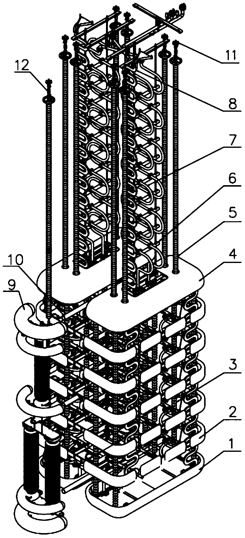
  • Figure 1
    Figure 1
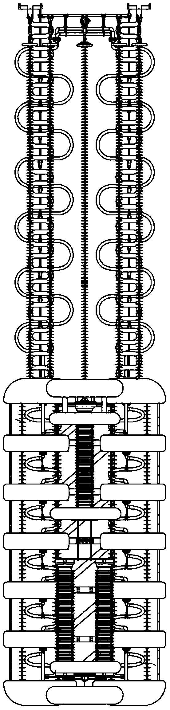
  • Figure 2
    Figure 2
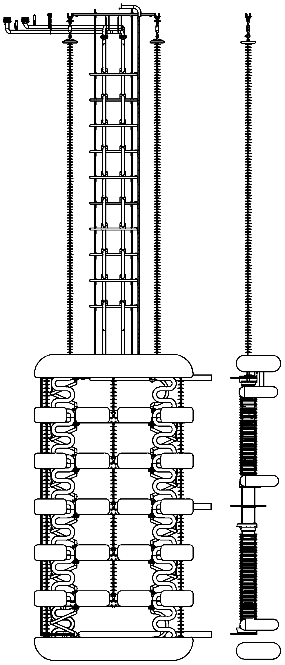
  • Figure 3
    Figure 3
Patent Text Reader

Abstract

The invention provides a novel valve tower of a thyristor converter valve. The novel valve tower comprises a valve hall, a valve tower body, a valve support (6) and a lightning arrester (9). The valve tower body and the lightning arrester (9) are hung on the lower edge of a steel beam on the top of the valve hall through a suspended insulator chain. The valve tower body is composed of a top shielding case (4), a bottom shielding case (1) and valve layers between the top shielding case (4) and the bottom shielding case (1). The valve tower body is composed of a left half tower body and a right half tower body. Each valve layer is composed of two converter valve modules (2). The valve layers and the bottom shielding case (1) are suspended below the top shielding case (4) through interlayer insulators (3) arranged between the adjacent valve layers and arranged between the valve layers and the bottom shielding case (1). By the adoption of the structure, the valve tower body and the steel beam on the top of the valve hall can swing relatively, the valve layers can also swing relatively, and therefore the valve tower is high in overall flexibly and good in anti-seismic effect.
Need to check novelty before this filing date? Find Prior Art

Description

technical field

[0001] The invention relates to a high-voltage direct current transmission equipment, in particular to a novel valve tower of a thyristor converter valve. Background technique

[0002] As a large-capacity and long-distance transmission technology, HVDC transmission is increasingly widely used in our provincial and inter-regional networking projects. In HVDC transmission, the converter valve is responsible for the AC-DC conversion function and is the core equipment of the converter station. It is composed of a large number of various components and has a complex structure. Therefore, a complete and reliable protection system is necessary.

[0003] In the application of high-voltage direct current transmission projects, low-voltage thyristors are usually used as commutation units and connected to each other in a certain way to obtain higher voltage levels and higher power outputs. When the voltage level reaches tens of kilovolts or even hundreds of kilovolts, ...

Examples

Embodiment Construction

[0027] The specific implementation manners of the present invention will be further described in detail below in conjunction with the accompanying drawings.

[0028] In order to thoroughly understand the embodiments of the present invention, the detailed structure will be set forth in the following description. Obviously, the practice of the embodiments of the invention is not limited to specific details familiar to those skilled in the art. Preferred embodiments of the present invention are described in detail below, however, the present invention may have other embodiments besides these detailed descriptions.

[0029] refer to figure 1 , figure 2 and image 3 , figure 1 It is a schematic diagram of the three-dimensional structure of the valve tower of the thyristor converter valve of the present invention; figure 2 It is the front view of the valve tower of the thyristor converter valve of the present invention; image 3 It is the left view of the valve tower of the ...