
Switch device, leaf spring manufacturing method and leaf spring

A switch device and leaf spring technology, which is applied in the field of leaf springs, can solve the problems such as the decline of fatigue characteristics of leaf springs, and achieve the effects of inhibiting the decline of fatigue characteristics and delaying oxidation

Active Publication Date: 2015-01-14
KK TOKAI RIKA DENKI SEISAKUSHO
View PDF4 Cites 3 Cited by
  • Summary
  • Abstract
  • Description
  • Claims
  • Application Information

AI Technical Summary

Problems solved by technology

However, if silver plating is also applied to the stress concentration part of the leaf spring, the fatigue characteristics of the leaf spring will be reduced.

Method used


Image

  • Switch device, leaf spring manufacturing method and leaf spring
  • Switch device, leaf spring manufacturing method and leaf spring
  • Switch device, leaf spring manufacturing method and leaf spring

Examples


Embodiment Construction

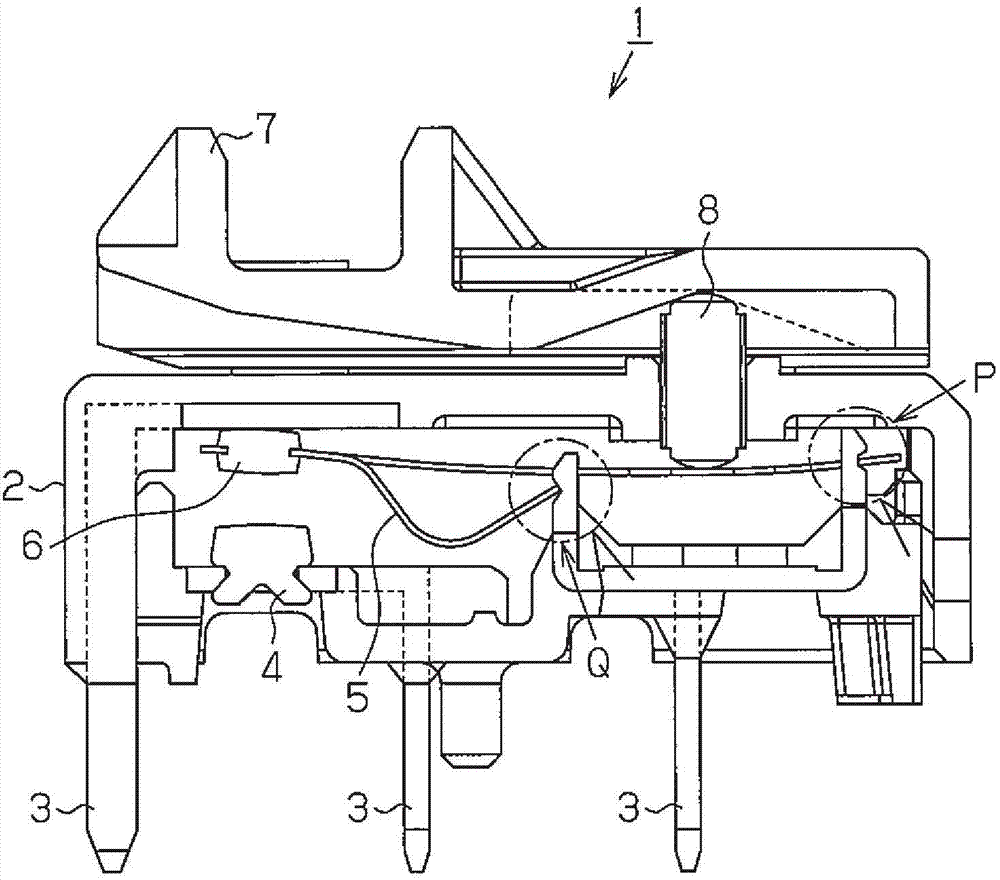
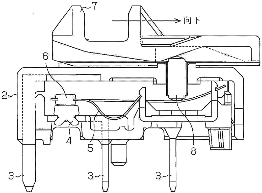
[0023] One embodiment of the switch device will be described below.

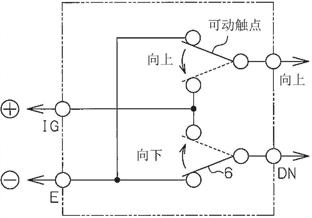
[0024] Such as figure 1 As shown, a power window switch 1 which is an example of a switch device includes an insulator 2 forming a support base. A plurality of (four in this example) terminals 3 are attached to the insulator 2 . exist figure 1 3 of the 4 terminals 3 are shown in . A fixed contact 4 is connected to a specific one of the four terminals 3 . In this example, the four terminals 3 are UP terminal, DN terminal, IG terminal, and E terminal. The UP terminal is provided in association with the upward movement of closing the door glass, and the DN terminal is provided in association with the downward movement of opening the door glass. The IG terminal is connected to the high potential side of the power supply, and the E terminal is connected to the low potential side of the power supply. In this example, the IG terminal is used for the specific terminal 3 above.

[0025] In the inner space of t...


PUM


Abstract

A switch device includes a terminal and a leaf spring supported by the terminal. The leaf spring is resiliently movable to produce a contact action. The leaf spring includes a metal plating applied to a portion that is in contact with and supported by the terminal. The metal plating is not applied to a portion of the leaf spring where stress concentrates when the leaf spring is resiliently moved.

Description

technical field [0001] The present invention relates to a switch device that generates contact motion based on elastic displacement of a leaf spring, a method for manufacturing the leaf spring, and the leaf spring. Background technique [0002] Patent Document 1 describes a switch device called a snap action model switch. In this switching device, the contact movement is generated based on the elastic displacement of the leaf spring. In this configuration, since the opening and closing of the contacts is quick and stable, the duration of the arc can be suppressed. Therefore, a longer lifetime of the switch can be expected. [0003] Patent Document 1 Japanese Patent Application Laid-Open No. 7-65681 [0004] In the switch device described above, since the leaf spring is supported by the terminal, the leaf spring is always in contact with the terminal. However, if abrasion occurs at the contact portion of the leaf spring and the terminal due to contact movement, abrasion p...

Claims


Application Information

Patent Timeline
IPC IPC(8): H01H5/18H01H11/00
CPCH01H2235/024H01H1/5844H01H15/102H01H2300/01
Inventor 竹内元哉武藤尊靖寺川胜利
Owner KK TOKAI RIKA DENKI SEISAKUSHO
Learn More