Check patentability & draft patents in minutes with Patsnap Eureka AI!

Automatic pay-off system

An automatic, pay-off reel technology, applied in cable laying equipment and other directions, can solve the problems of wasting manpower and material resources, large resistance, etc.

Inactive Publication Date: 2015-03-04
ELECTRIC POWER OF HENAN LUOYANG POWER SUPPLY +1
View PDF4 Cites 0 Cited by
  • Summary
  • Abstract
  • Description
  • Claims
  • Application Information

AI Technical Summary

Benefits of technology

The technology described by this inventor improves upon previous methods for producing certain types of chemicals that were previously used or discovered. This results from its unique design with several benefits such as improved efficiency compared to existing techniques while also being able to produce more complex compounds than before it was possible due to new technologies developed during production.

Problems solved by technology

The technical problem addressed by this patented technology relates to how efficiently lay out cords on underground pipes during maintenance tasks or other similar activities that require multiple people's labor hours for precise placement.

Method used


Image

  • Automatic pay-off system
  • Automatic pay-off system

Examples


Embodiment Construction

[0011] The technical solutions of the present invention will be further described in detail below in conjunction with the accompanying drawings and embodiments.

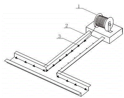
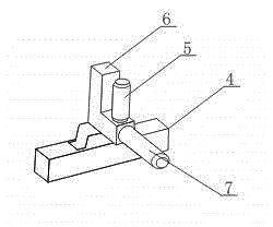
[0012] Such as figure 1 Shown, a kind of automatic pay-off system, it comprises pay-off stand and pay-off reel device, pay-off reel device comprises pay-off reel 1 and pay-off support 3, pay-off reel 1 is installed on the rotating shaft on the pay-off stand, And one end of the pay-off frame shaft is connected with a motor, the pay-off bracket 3 is arranged on the ditch wall in the cable trench 2, the pay-off bracket 3 includes a fixed seat 4 arranged on the side wall of the cable trench and a fixed seat arranged on the fixed seat. The L-shaped support 6 on the surface is respectively provided with a horizontal connection shaft and a vertical connection shaft on the end of the horizontal section of the L-shaped support 6 and the upper end surface of the horizontal section, and is respectively sleeved on the horizontal...


PUM


Abstract

The invention discloses an automatic pay-off system. The automatic pay-off system comprises a pay-off rack and a pay-off spool device; the pay-off spool device comprises a pay-off spool and a pay-off bracket, wherein the pay-off spool is mounted on a rotating shaft of the pay-off rack; a motor is connected to one end part of the rotating shaft of the pay-off rack; the pay-off bracket is arranged on the inner wall of a cable duct, comprising a fixing seat and an L-shaped bracket, wherein the L-shaped bracket is arranged on the upper surface of the fixing seat; a horizontal connecting shaft and a vertical connecting shaft are respectively arranged at the end part of a horizontal section of the L-shaped bracket and the upper end surface of the horizontal section; a hollow rotating shaft and a vertical rotating shaft which are both of a hollow structure respectively sleeve the horizontal connecting shaft and the vertical connecting shaft; in addition, the horizontal rotating shaft and the vertical rotating shaft can rotate freely; a gap through which a cable passes is formed between the vertical rotating shaft and the vertical section of the L-shaped bracket.

Description


Claims


Application Information

Patent Timeline
Owner ELECTRIC POWER OF HENAN LUOYANG POWER SUPPLY
Features
  • R&D
  • Intellectual Property
  • Life Sciences
  • Materials
  • Tech Scout
  • Unparalleled Data Quality
  • Higher Quality Content
  • 60% Fewer Hallucinations
Learn More