Source drive circuit and control method thereof

A source drive and control method technology, applied in control/regulation systems, electrical components, electronic switches, etc., can solve the problem of prolonged power consumption during the disconnection process of the main switch, avoid delay, suppress EMI, reduce The effect of additional power consumption

Active Publication Date: 2017-09-01
SILERGY SEMICON TECH (HANGZHOU) CO LTD
View PDF4 Cites 0 Cited by
  • Summary
  • Abstract
  • Description
  • Claims
  • Application Information

AI Technical Summary

Problems solved by technology

However, the adjustment resistor with a large resistance value prolongs the turn-off process of the main switch and generates additional power dissipation

Method used


Image

  • Source drive circuit and control method thereof
  • Source drive circuit and control method thereof
  • Source drive circuit and control method thereof

Examples


Embodiment Construction

[0034] Several preferred embodiments of the present invention will be described in detail below with reference to the accompanying drawings, but the present invention is not limited to these embodiments. The present invention covers any alternatives, modifications, equivalent methods and schemes made within the spirit and scope of the present invention.

[0035] In order to provide the public with a thorough understanding of the present invention, specific details are set forth in the following preferred embodiments of the present invention, but those skilled in the art can fully understand the present invention without the description of these details.

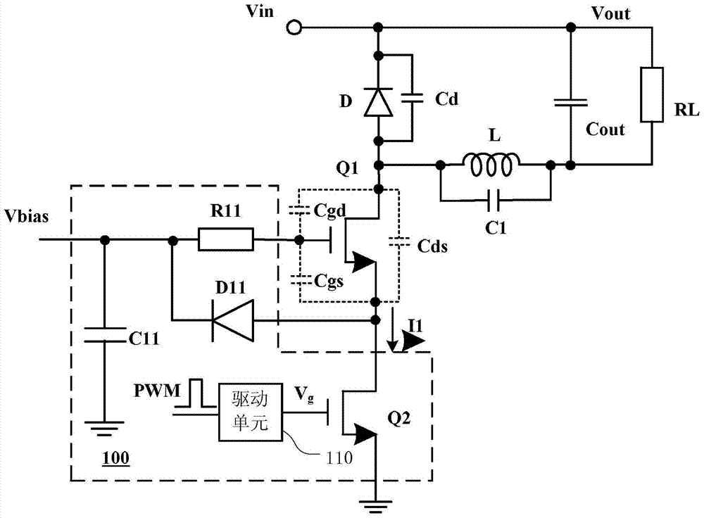
[0036] figure 1It is a schematic block diagram of a BUCK converter using a source drive method. The BUCK converter includes an input terminal Vin and an output terminal Vout, which are respectively used for receiving, for example, a rectified input voltage and supplying power to a load RL. The main switching tube Q1, the in...


PUM


Abstract

Disclosed are a source driving circuit and a control method thereof. The source drive circuit includes: a control transistor, connected between the second terminal of the main switch tube and the ground; a power supply capacitor, the two ends of the power supply capacitor receive a substantially constant bias voltage; and a feed diode, the feed diode The cathode is connected to the control terminal of the main switch tube, and the anode is connected to the second terminal of the main switch tube, wherein the control transistor is periodically turned on and off, so that the main switch tube follows the control transistor and correspondingly conducts On and off, the conduction period of the main switch tube includes the first stage from the off state to the full conduction state and the second stage in the full conduction state, in the first stage, the The control transistor provides an approximately constant startup current. The source drive circuit prolongs the conduction time of the main switch tube, thereby advantageously suppressing EMI. At the same time, it also avoids the delay of the disconnection process of the main switch tube, thereby reducing the additional power consumption.

Description

technical field [0001] The present invention relates to a power converter, and more particularly, to a source drive circuit for a power converter and a control method thereof. Background technique [0002] The source driving method is widely used in various types of power converters due to its low power consumption and high efficiency. The working principle of the source driving mode is that the gate voltage of the main switching tube is fixed at a certain value, and the source voltage of the main switching tube is changed through the source driving circuit to control the switching state of the main switching tube. [0003] In the source drive circuit, the control transistor is cascaded with the main switch. For example, the drain of the control transistor is connected to the source of the main switching transistor, and the source of the control transistor is connected to the ground. The gate of the control transistor receives a PWM signal to be turned on and off periodica...

Claims


Application Information

Patent Timeline
Patent Type & Authority Patents(China)
IPC IPC(8): H02M1/08H02M3/156H02M3/335
CPCH02M1/088H02M3/155H02M3/335H02M1/0054H02M3/158H03K17/602H03K17/6871Y02B70/10
Inventor 邓建刘国家
Owner SILERGY SEMICON TECH (HANGZHOU) CO LTD
Why Eureka
Try Eureka