Anti-rotation tool for chain wheel

A sprocket and anti-rotation technology, used in workpiece clamping devices, manufacturing tools, hand-held tools, etc., can solve the problems of not designing anti-rotation structures and affecting installation quality.

Inactive Publication Date: 2015-03-25
刘兴永
View PDF0 Cites 1 Cited by
  • Summary
  • Abstract
  • Description
  • Claims
  • Application Information

AI Technical Summary

Problems solved by technology

[0002] Some sprockets on the engine need to be fixed and cannot be rotated during installation, so as to prevent the corresponding installation position from being wrong and affect the subsequent assembly of other parts. Some sprockets themselves do not have an anti-rotation structure,

Method used


Image

  • Anti-rotation tool for chain wheel
  • Anti-rotation tool for chain wheel
  • Anti-rotation tool for chain wheel

Examples


Example Embodiment

[0010] The present invention will be further described in detail below through specific implementation examples in conjunction with the accompanying drawings.

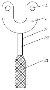
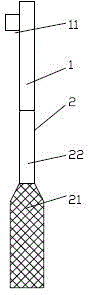
[0011] figure 1 , figure 2 , image 3 The sprocket anti-rotation tool provided by the present invention is shown, including a U-shaped tooling plate 1. Two straight arms of the U-shaped tooling plate 1 are respectively provided with positioning pins 11 matching the process holes of the sprocket; U-shaped tooling plate 1 The distance between the two straight arms of the sprocket is greater than the maximum size of the head of the mounting bolt in the center hole of the sprocket; the closed end of the U-shaped tooling plate 1 is welded with a cylindrical handle 2. The handle is divided into a hand-held knurled section 21 and a smooth section 22. The smooth section 22 is connected with the U-shaped tooling plate 1. Both the U-shaped tooling plate 1 and the handle 2 are steel parts.

[0012] The foregoing descriptions are on...


PUM


Abstract

The invention discloses an anti-rotation tool for a chain wheel, and belongs to the technical field of engine tools. The anti-rotation tool comprises a U-shaped tool plate, wherein positioning pins matched with chain wheel process holes are arranged on two straight arms of the U-shaped tool plate respectively; the distance between the two straight arms of the U-shaped tool plate is greater than the maximum size of the head of a mounting bolt of a center hole of the chain wheel; a cylindrical handle is welded at the sealed end of the U-shaped tool plate, and is divided into a handheld knurled section and a smooth section; the smooth section is connected with the U-shaped tool plate. According to the anti-rotation tool, anti-rotation fixation is ensured, and meanwhile, influence on the mounting of a center bolt is eliminated; during mounting, the handheld knurled section of the handle is handheld, so that the influence of slip on mounting is avoided, and reliability and effectiveness are achieved.

Description

Technical field [0001] The invention relates to the technical field of engine tooling, in particular to a sprocket anti-rotation tooling. Background technique [0002] Some sprockets on the engine need to be fixed and cannot be rotated during installation to prevent the installation of the corresponding position from being wrong and affect the subsequent assembly of other parts. Some sprockets are not designed with anti-rotation structure, which requires the use of self-made tooling. For anti-rotation, such as camshaft sprocket, the center hole is a bolt installation hole, and there are process holes arranged around the center hole. During the tightening process, it will follow the tightening bolt to rotate, which affects the installation quality. Summary of the invention [0003] The purpose of the present invention is to provide a sprocket anti-rotation tool to solve the above-mentioned problems. [0004] In order to achieve the purpose of the present invention, the technical sol...

Claims


Application Information

Patent Timeline
IPC IPC(8): B25B11/02B25B27/14
CPCB25B11/02B25B27/14
Inventor 刘兴永
Owner 刘兴永
Why Eureka
Try Eureka