Adjustable mechanical anti-loosing positioning device for rotating shaft and use method of adjustable mechanical anti-loosing positioning device
A positioning device and adjustable technology, applied in mechanical equipment, rigid brackets of bearing components, bearing components, etc., can solve the problems of inability to apply precise positioning and fixation, anti-rotation and positioning methods cannot be fixed, etc. The effect of structural stabilization
- Summary
- Abstract
- Description
- Claims
- Application Information
AI Technical Summary
Problems solved by technology
Method used
Image
Examples
Embodiment 1
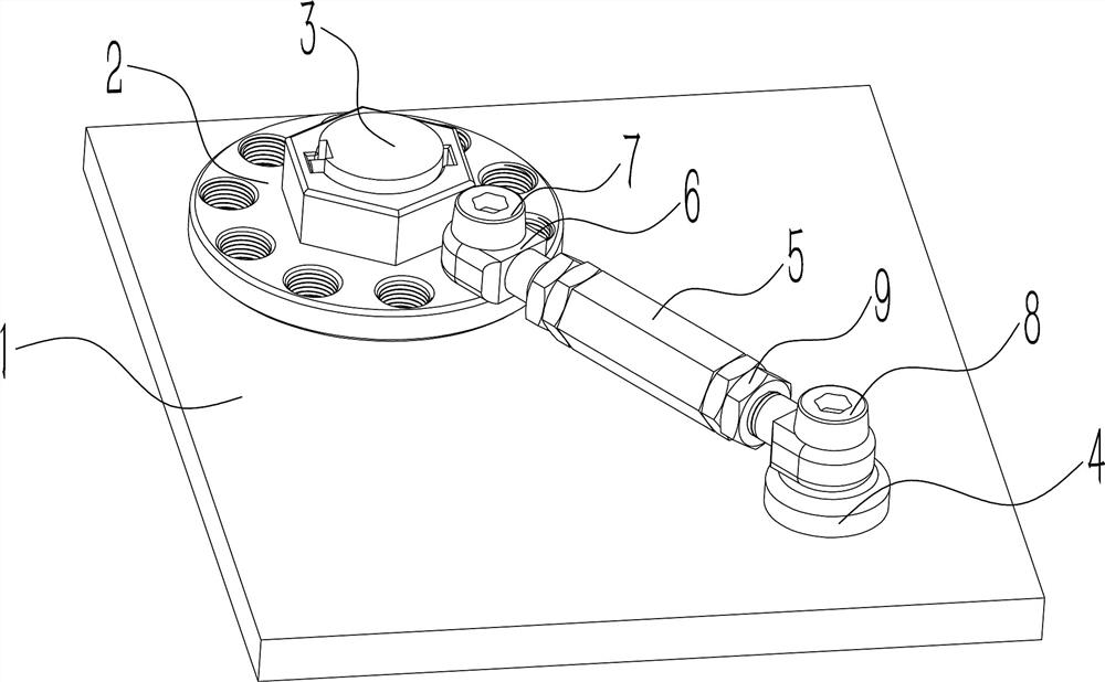
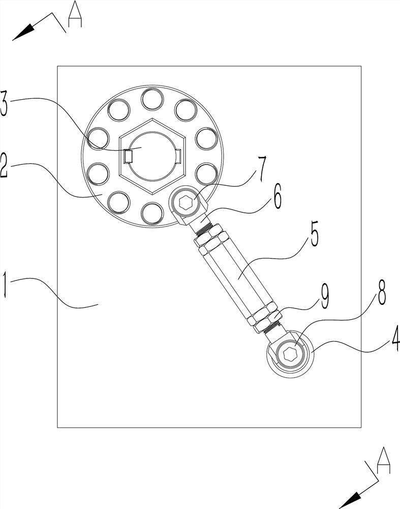
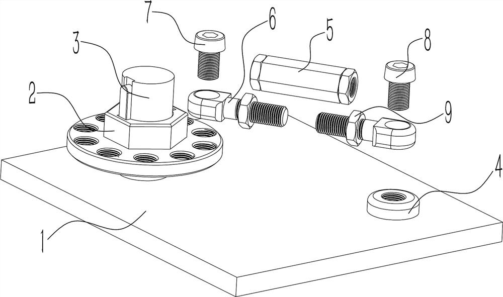
[0025] Such as Figure 1~4 As shown, an adjustable mechanical anti-loosening positioning device for a rotating shaft and its use method include a base 1 and a rotating shaft 3, and the feature is that: the end of the rotating shaft 3 is fixed with a flange positioning seat 2, and one side of the base 1 A fixing seat 4 is provided, and a thread sleeve 5 is arranged between the flange positioning seat 2 and the fixing seat 4. The two ends of the thread sleeve 5 are provided with threaded screw rods 6. The rod 6 is fixed on the fixing seat 4 , and the screw rod 6 at the other end is fixed on the flange positioning seat 2 . With this structure, after the rotating shaft 3 is rotated and assembled, the flange positioning seat 2 is fixed on the end of the rotating shaft 3 through a key, and the flange positioning seat 2 and the fixing seat 4 are connected by the thread sleeve 5 and the screw rod 6 at both ends, so that the flange positioning seat 2 and the fixing seat 4 can be connec...
Embodiment 2
[0034] Such as Figure 1~4 As shown, further description in conjunction with Example 1: During the processing of the base body 1, a fixed seat 4 is provided on the side where the rotating shaft 3 is installed, and after the rotating shaft 3 is assembled, the flange positioning seat 2 is installed at the end of the rotating shaft 3 through a key; Turn the wire sleeve 5 to adjust the length of the screw rod 6 at both ends, so that the screw rod 6 at one end is fixed in the hole on the side of the flange positioning seat 2 through the first fixed pile 7, and the screw rod 6 at the other end passes through the second fixed pile 8 fixed in the fixed seat 4; turn the wire sleeve 5 to shrink the screw rod 6 at both ends, so that the screw rod 6 connects the distance between the fixed flange positioning seat 2 and the fixed seat 4, thereby fixing the rotation of the rotating shaft 3; The nut 9 on the rod 6, so that the nut 9 abuts against the end of the wire sleeve 5, thereby further ...
PUM
 Abstract
Description
Claims
Application Information
 - R&D
- Intellectual Property
- Life Sciences
- Materials
- Tech Scout
- Unparalleled Data Quality
- Higher Quality Content
- 60% Fewer Hallucinations
Browse by: Latest US Patents, China's latest patents, Technical Efficacy Thesaurus, Application Domain, Technology Topic, Popular Technical Reports.
© 2025 PatSnap. All rights reserved.Legal|Privacy policy|Modern Slavery Act Transparency Statement|Sitemap|About US| Contact US: help@patsnap.com


