Planar optical waveguide with lensed end face

A planar optical waveguide and end face technology, which is applied in the field of microwave photonics and optical communication, can solve the problems of difficult center alignment of the optical axis and unstable optical path, so as to overcome the unstable optical path, realize beam collimation and focusing, and simplify coupling structure effect

Inactive Publication Date: 2015-03-25
INST OF SEMICONDUCTORS - CHINESE ACAD OF SCI
View PDF3 Cites 14 Cited by
  • Summary
  • Abstract
  • Description
  • Claims
  • Application Information

AI Technical Summary

Problems solved by technology

[0005] Aiming at the deficiencies described in the background technology, the main purpose of the present invention is to provide a planar optical waveguide whose end face is lensed, so as to realize the integration of the planar optical waveguide and the lens, overcome the instability of the optical path caused by the separation of the lenses, and align the center of the optical axis Difficulties and other issues, simplify the coupling structure

Method used


Image

  • Planar optical waveguide with lensed end face
  • Planar optical waveguide with lensed end face
  • Planar optical waveguide with lensed end face

Examples


Embodiment Construction

[0018] In order to make the objectives, technical solutions, and advantages of the present invention clearer, the following further describes the present invention in detail with reference to specific embodiments and drawings.

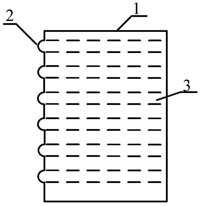
[0019] The lensed end face of the planar optical waveguide provided by the present invention forms a spherical lens end face with collimating or focusing functions by lensing the incident end face of the planar optical waveguide, thereby realizing the integration of the lens and the planar optical waveguide, and overcome The problem of instability of the optical path caused by the separation of the lens and the planar optical waveguide, difficulty in the center alignment of the optical axis, etc. is solved, the coupling structure is simplified, and it can be used in both directions to realize the beam collimation and focusing functions respectively.

[0020] Such as figure 1 As shown, figure 1 It is a schematic diagram of a planar optical waveguide with lens...


PUM


Abstract

The invention discloses a planar optical waveguide with a lensed end face. The planar optical waveguide comprises a planar optical waveguide array and a coupler. The planar optical waveguide array comprises a plurality of parallel planar optical waveguide bodies, and the planar optical waveguide bodies are provided with lensed spherical mirror end face bodies with the collimating or focusing function. The coupler is used for supporting and fixing the planar optical waveguide array. According to the planar optical waveguide with the lensed end face, lensed processing is carried out on the incident end faces of the planar optical waveguide bodies, the spherical mirror end faces with the collimating or focusing function are formed, integration of a lens and the planar optical waveguide bodies is achieved, the problems that due to separation of the lens and the planar optical waveguide bodies, the light path is not stable, and the center of an optical axis is aligned difficulty are solved, the coupling structure is simplified, the planar optical waveguide can be used in two directions, and the light beam collimating and focusing functions are achieved.

Description

Technical field [0001] The invention relates to a planar optical waveguide with lensed end faces, which belongs to the technical fields of microwave photonics and optical communication. Background technique [0002] In optical fiber communication, optical signals need to be transmitted in waveguides, so the coupling between the waveguide and the light source becomes particularly important. Waveguide coupling is to introduce the light emitted from the light source into or out of the waveguide in a certain way. [0003] According to the mode coupling theory, optical coupling is essentially the mode field matching between the light source and the waveguide. The traditional method is to add a separate single lens or "double lens + isolator" between the waveguide and the light source, and need to use a six-dimensional precision fine-tuning frame to accurately adjust its position, which has poor stability and complex structure; or Directly align the light source with the waveguide, the...

Claims


Application Information

Patent Timeline
Patent Type & Authority Applications(China)
IPC IPC(8): G02B6/122G02B6/124
CPCG02B6/1245G02B6/122
Inventor 张志珂王欣刘宇祝宁华
Owner INST OF SEMICONDUCTORS - CHINESE ACAD OF SCI
Why Eureka
Try Eureka