Constant DC bus voltage permanent magnet generator set based on prime mover speed regulation

A permanent magnet generator and bus voltage technology, which is applied to the control of generators, electrical components, control systems, etc., can solve the problem of the large output voltage range of permanent magnet generators, the difficulty of maintaining a constant generator terminal voltage, and the difficulty of maintaining power generation Problems such as the output voltage of the machine, to achieve the effect of reducing power electronic devices, saving control costs, and simple structure

Active Publication Date: 2018-04-10
SHENYANG POLYTECHNIC UNIV
View PDF10 Cites 0 Cited by
  • Summary
  • Abstract
  • Description
  • Claims
  • Application Information

AI Technical Summary

Problems solved by technology

The utility model patent "Speed-adjustable and fuel-saving diesel generator set powered tire-type gantry container crane" (200920108181.4) is aimed at adjustable-speed diesel generator sets, which adjust the operating speed of diesel generator sets according to changes in load power to achieve energy-saving operation. The electric excitation synchronous generator is still used, and the variable speed range of the diesel engine is relatively large, so it is difficult to maintain the output voltage of the generator within a certain range to meet the requirements of the variable range of the input voltage of the inverter; the invention patent "a variable speed permanent Magnetic AC generator system and its dual-port voltage stabilization control method" (201210205337.7) is based on the premise that the DC output terminal voltage of the existing generator system is stable, and when the generator speed changes significantly, it can overcome the significant change in the AC output terminal voltage. To realize the dual-port voltage regulation of the permanent magnet alternator system, the key point is how to realize the voltage regulation of the AC output terminal by controlling the AC and DC axis current of the motor when the generator speed changes, which requires rotor position, speed, and AC voltage detection modules And complex controllers, and it is difficult to maintain a constant terminal voltage of the generator when the speed of the prime mover varies widely; the invention patent "a frequency conversion energy-saving diesel generator set for a communication base station" (201110344828.5) is to output the permanent magnet generator The AC power is converted into a stable DC power and directly supplied to the DC load. The speed of the diesel engine and the output voltage of the permanent magnet generator vary widely, so a controllable and uncontrollable rectification module is required; the utility model patent "inverter AC permanent magnet generator set" (200620163948.X) uses a mechanical governor, introduces the composition and working principle of the generator set, but does not explain its feasibility; utility model patent "a permanent magnet generator set voltage stabilizing device" (201220575418.1) On the basis of the original engine speed feedback signal, the generator voltage feedback signal is added. The goal is to maintain the voltage and frequency of the generator within the specified range. Since the voltage adjustment rate of the permanent magnet generator is about 10%, the variation range Larger, it is more difficult to achieve this goal
Although these patents have made different improvements to the traditional electric excitation generator set or permanent magnet generator set, they all have certain limitations and the control is relatively complicated

Method used


Image

  • Constant DC bus voltage permanent magnet generator set based on prime mover speed regulation
  • Constant DC bus voltage permanent magnet generator set based on prime mover speed regulation

Examples


Embodiment 1

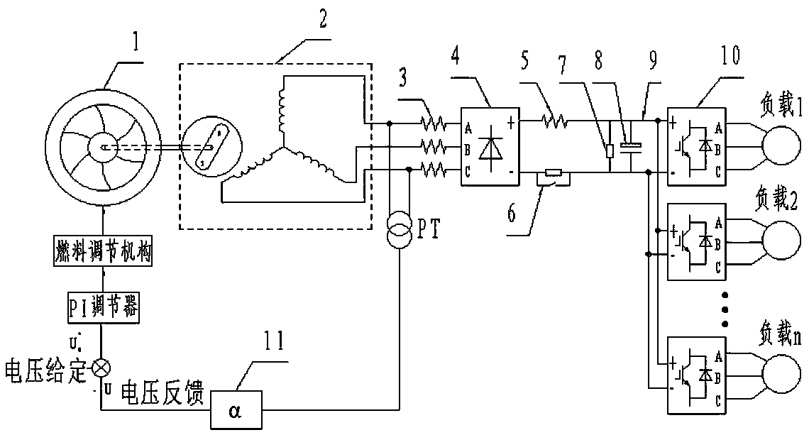
[0034] figure 1 It is a schematic diagram of the permanent magnet generator set with constant DC bus voltage based on prime mover speed regulation, as shown in figure 1As shown, it consists of prime mover 1, permanent magnet generator 2, AC reactor 3, uncontrollable rectification module 4, DC reactor 5, pre-charging circuit 6, braking resistor 7, capacitor group 8, DC bus 9, voltage sensor PT, feedback coefficient 11, given voltage, PI regulator, fuel regulating mechanism, inverter 10 and various loads. The energy flow direction of the power supply system is: the prime mover 1 drives the permanent magnet generator 2 to rotate, wherein the prime mover 1 can be an internal combustion engine, a gas turbine, a water turbine, etc., and the three-phase alternating current generated by the permanent magnet generator 2 passes through the uncontrollable rectification module 3 Afterwards, it becomes a DC power supply, and the DC power supply supplies power to the load through the inver...


PUM


Abstract

The invention relates to a constant DC bus voltage permanent magnet generator set based on prime mover speed regulation. The three-phase alternating current generated by the permanent magnet generator under the drive of the prime mover is rectified and filtered to obtain direct current with constant voltage amplitude to supply power to the load; Voltage feedback and PI adjustment realize the static-difference adjustment of the generator output voltage. During this process, the fuel control valve changes with the load change, realizing the purpose of matching the output power of the prime mover with the load power. The invention has simple structure, easy implementation, low cost, high efficiency and strong reliability, and has great practical value.

Description

technical field [0001] The invention belongs to the field of electrical engineering, and relates to a constant DC bus voltage permanent magnet generator set based on prime mover speed regulation. Background technique [0002] This patent is funded by the National 863 Project (2012AA061303) and the National Major Scientific Instrument and Equipment Development Project (2012YQ05024207). In recent years, the shortage of electricity caused by economic development and unbalanced distribution of resources has become prominent, making the role of independent power sources more obvious in the development of the national economy. The independent power supply has been widely used as the main power supply or backup power supply in many fields such as ships, aviation, communications, military affairs, hospitals, emergency response, and disaster relief. Cooperating with the large power grid, the independent power supply can greatly improve the reliability of power supply, and can mainta...

Claims


Application Information

Patent Timeline
Patent Type & Authority Patents(China)
IPC IPC(8): H02P9/04H02P101/25
CPCH02P9/04
Inventor 张炳义何功飞冯桂宏张化光
Owner SHENYANG POLYTECHNIC UNIV
Why Eureka
Try Eureka