A Continuously Variable Rate Digital Shaping Filter Processing Method

A digital shaping and filtering technology, applied in the direction of digital technology network, impedance network, electrical components, etc., can solve the problems such as the data rate cannot be continuously variable, the number of filter stages is large, the resource consumption is large, and the hardware consumption is less. , the effect of less hardware resources and constant filter coefficients

CN104539262BActive Publication Date: 2017-07-28BEIJING RES INST OF TELEMETRY +1
5 Cites 0 Cited by

Patent Information

Authority / Receiving Office
CN · China
Patent Type
Patents(China)
Current Assignee / Owner
Publication Date
2017-07-28

Smart Images

  • Figure 1
    Figure 1
  • Figure 2
    Figure 2
  • Figure 3
    Figure 3
Patent Text Reader

Abstract

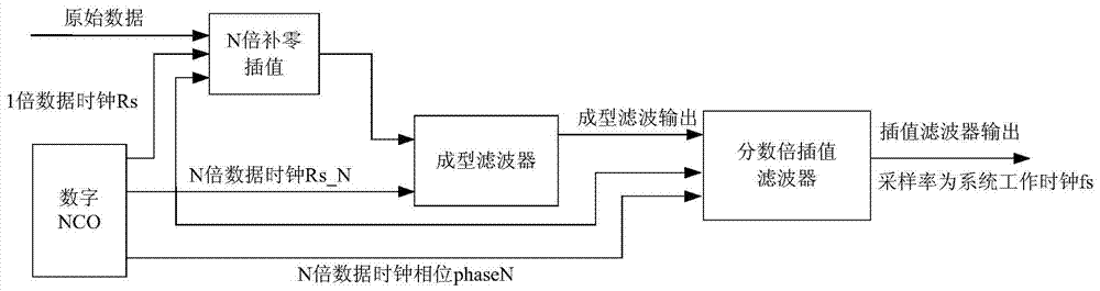
The invention provides a digital-shaping filtering method for a continuous and variable speed. The digital-shaping filtering method for the continuous and variable speed comprises the steps that (1) a one-time data clock signal A1 and an N-time data clock signal AN are generated through a digital NCO, (2) an input signal is received according to the data clock signal A1, (3) N-time zero-fill interpolation is conducted on the received signal by means of the data clock signal AN, (4) the signal subjected to interpolation is filtered by means of a digital shaping filter, and (5) variable-sampling-rate interpolation filtering is conducted on the signal subjected to shaping filtering. According to the continuous variable-speed digital-shaping filtering method, the shaping filter with the fixed coefficient and an interpolation filter with a variable coefficient are used for shaping filtering and interpolation filtering respectively, shaping filtering and interpolation filtering of different speed signals can be achieved, the method can be applied to a digital modulator with continuous and variable data speed, the filtering method is easy to realize, hardware resource consumption is low, and practicability is high.
Need to check novelty before this filing date? Find Prior Art

Description

technical field

[0001] The invention relates to a digital shaping filter processing method, in particular to a continuously variable rate digital shaping filtering processing method. Background technique

[0002] In modern wireless communication systems, in order to effectively use the channel, the signal spectrum must be compressed before the signal is transmitted, so as to improve the frequency band utilization under the premise of eliminating inter-symbol interference and achieving the best detection. Pulse-shaping filtering for baseband data is an effective way to improve spectrum utilization. With the continuous development of wireless communication systems, the transmission signal rate is often required to be variable or even continuously variable. For example, satellite communication systems usually change the transmission rate according to the application bandwidth requirements.

[0003] In the existing digital shaping filter design, since the output sampling rate o...

Examples

Embodiment

[0073] In this embodiment, the system operating frequency fs is 100MHz, and the digital shaping filter processing method with continuously variable rate of the present invention is used to perform 4 times shaping filtering and variable rate interpolation filtering processing on data with a code rate of Rb=6.15Mbps, that is, positive Integer N=4.

[0074] Among them, the variable-rate interpolation filtering process is realized by a fractional multiple interpolation filter, which is composed of a 48-order transverse FIR filter and a ROM table bound with filter coefficients, wherein the coefficients of the FIR filter are 16-bit quantization, 8-bit quantization is used for the clock phase, and the storage capacity of the ROM table of the binding filter coefficient is 48*16*2 8 =196608bit.

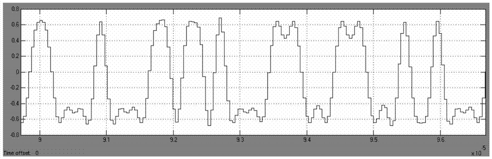
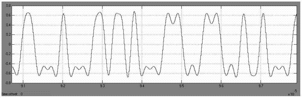
[0075] Through simulation processing, it can be obtained that the time-domain waveform of the data after 4 times shaping filtering is as follows: figure 2 As shown, the spectrogram of the d...