Catalyst feeding device for polymerization process of ultra-high molecular weight polyethylene and application

An ultra-high molecular weight, polymerization process technology, applied in the field of catalyst feeding devices, can solve problems such as blockage of catalyst feeding pipelines, and achieve the effects of reducing agglomeration, reducing the proportion of large particles, and increasing bulk density

Active Publication Date: 2015-04-29
CHINA PETROLEUM & CHEM CORP
View PDF5 Cites 5 Cited by
  • Summary
  • Abstract
  • Description
  • Claims
  • Application Information

AI Technical Summary

Problems solved by technology

The unique casing-type feeding method of the device can realize the online mixing of the catalyst feeding stage, and the spray structure can also effectively promote the dispersion of the catalyst after entering the polymerization tank, reduce the catalyst agglomeration phenomenon, improve the agglomeration phenomenon in the polymerization process, and at the same time Improve the problem of catalyst feed pipeline blockage

Method used


Image

  • Catalyst feeding device for polymerization process of ultra-high molecular weight polyethylene and application
  • Catalyst feeding device for polymerization process of ultra-high molecular weight polyethylene and application
  • Catalyst feeding device for polymerization process of ultra-high molecular weight polyethylene and application

Examples


Embodiment 1

[0046] Catalyst feed unit for UHMWPE polymerization process:

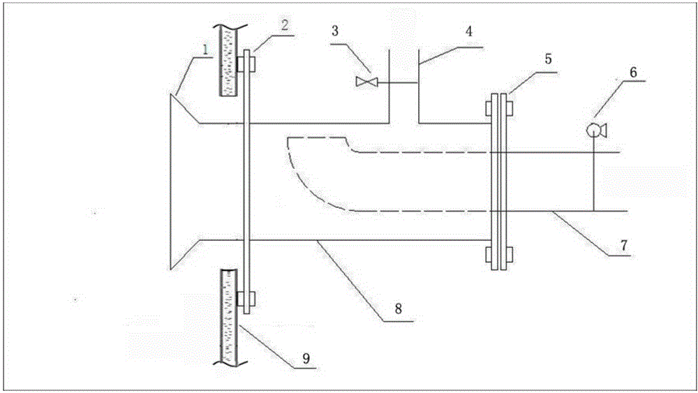
[0047] Such as figure 1 Shown, comprise catalyst feeding pipe 7, metering pump 6 is arranged on catalyst feeding pipe 7, catalyst premixing pipe 8 is arranged on catalyst feeding pipe 7 outer axis, catalyst feeding pipe 7 and catalyst premixing pipe 8 pass through the first method The flange 5 is connected, the catalyst premixing pipe 8 is provided with a solvent feed pipe 4, the solvent feed pipe 4 is provided with an electromagnetic flow regulating valve 3, and the catalyst premixing pipe 8 is connected to the polymerization kettle 9 through the second flange 2. The catalyst feeding device can be connected to the side wall of the polymerization kettle 9 . The end of the catalyst feeding pipe 7 near the end of the polymerization kettle 9 is a 90-degree elbow. The ends are 90 degree elbows. The gap between the port of the 90-degree elbow and the inner wall of the catalyst premixing pipe 8 is 4 cm. The port wher...

Embodiment 2

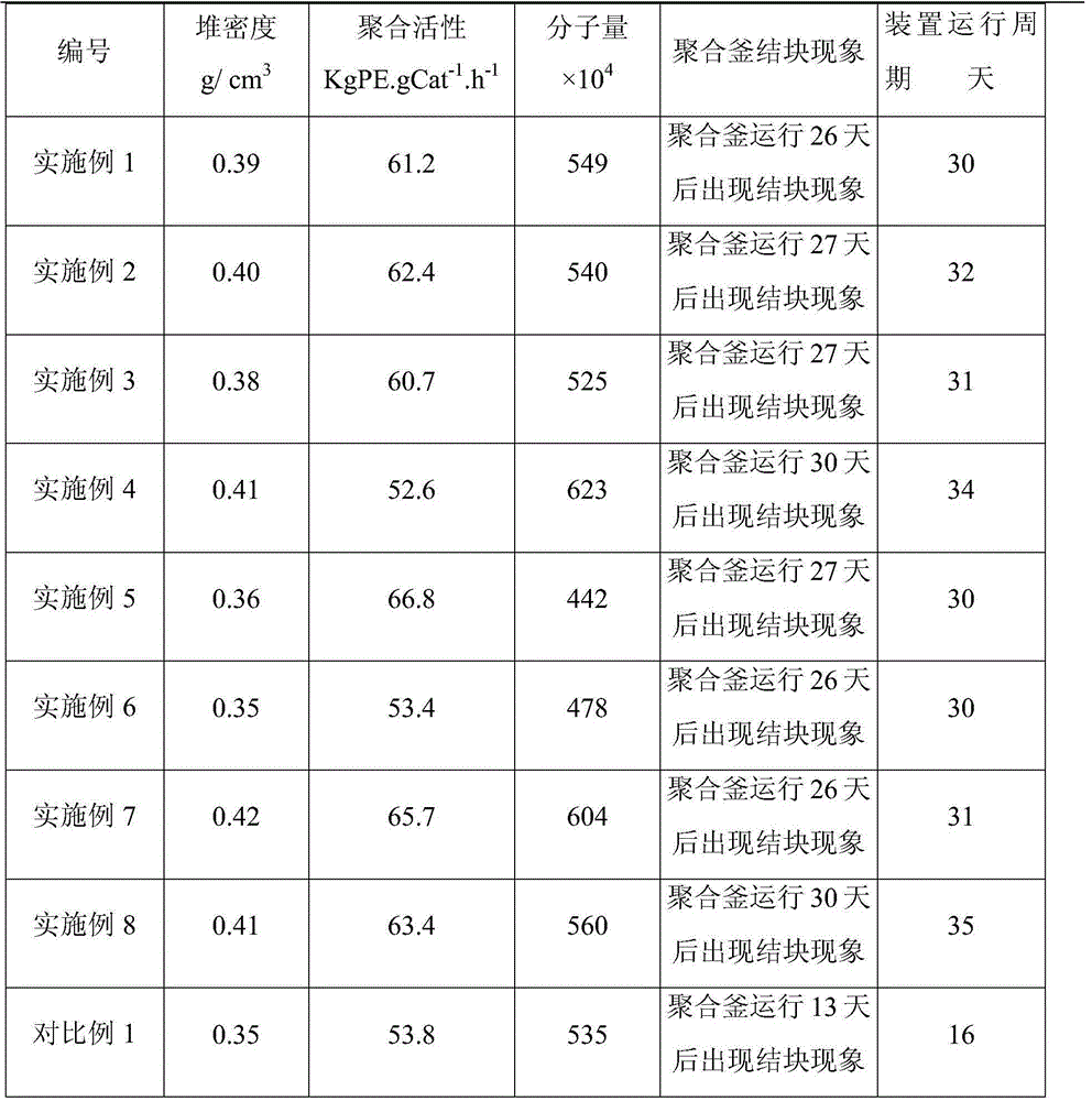
[0055] The ultra-high molecular weight polyethylene resin was prepared using the same device and method as in Example 1, but the solvent flow rate of the outer pipe of the catalyst feed pipe was set at 25 L / min. The polymerization performance and resin performance are shown in Table 1 and Table 2.

Embodiment 3

[0057] The ultra-high molecular weight polyethylene resin was prepared with the same device and method as in Example 1, but the flow rate of the catalyst slurry in the catalyst feed pipe was set at 0.5 L / min. The polymerization performance and resin performance are shown in Table 1 and Table 2.


PUM


Abstract

The invention belongs to the field of macromolecules, in particular to a catalyst feeding device for a polymerization process of ultra-high molecular weight polyethylene and application. The catalyst feeding device comprises a catalyst feeding pipe, wherein a metering pump is arranged on the catalyst feeding pipe, and a catalyst premixing pipe is arranged at an outer shaft of the catalyst feeding pipe; the catalyst feeding pipe is connected with the catalyst premixing pipe through a first flange, and a solvent feeding pipe is arranged on the catalyst premixing pipe; an electromagnetic flow regulating valve is arranged on the solvent feeding pipe, and the catalyst premixing pipe is connected with a polymerizing vessel through a second flange. The online mixing at a catalyst feeding stage is realized due to the unique sleeve type feeding way of the device, a spray structure promotes dispersion of a catalyst after entering the polymerizing vessel, the catalyst agglomeration phenomenon is reduced, the agglomeration phenomenon in the polymerizing process is improved, and the blockage of the catalyst feeding pipe is avoided at the same time. The invention further provides the application of the catalyst feeding device, the prepared ultra-high molecular weight polyethylene polymerisate is uniform in granule shape, the bulk density is increased, and the proportion of large particles is obviously reduced.

Description

technical field [0001] The invention belongs to the field of macromolecules, and in particular relates to a catalyst feeding device and its application for an ultra-high molecular weight polyethylene polymerization process. Background technique [0002] Ultra-high molecular weight polyethylene (UHMWPE) refers to a linear structure polyethylene with a viscosity average molecular weight of more than 1.5 million. Because the molecular weight of UHMWPE is as high as one million or even several million, it has excellent impact resistance, self-lubrication, chemical corrosion resistance, stress crack resistance, electrical insulation, wear resistance and other properties. Due to its unique performance advantages, UHMWPE is widely used in many fields such as textile, papermaking, transportation, packaging, machinery, chemical industry, mining, petroleum, agriculture, construction, electrical appliances, medical treatment, sports and refrigeration technology, especially suitable for...

Claims


Application Information

Patent Timeline
Patent Type & Authority Applications(China)
IPC IPC(8): C08F110/02C08F2/01C08F2/14B01J4/00
Inventor 李晓庆周建勇李留忠严婕毕晓龙齐立芳李功韬
Owner CHINA PETROLEUM & CHEM CORP
Why Eureka
Try Eureka