Antenna for vehicle with light-emitting bodies

A technology for illuminants and vehicles, which is applied to antennas, antenna equipment with additional functions, vehicle components, etc., can solve the problems of inability to establish communication, reduced communication sensitivity, and reduced antenna directivity, and achieves improved visual confirmation performance and good communication. The effect of sensitivity

Inactive Publication Date: 2015-05-06
HONDA LOCK MFG CO LTD
View PDF6 Cites 6 Cited by
  • Summary
  • Abstract
  • Description
  • Claims
  • Application Information

AI Technical Summary

Problems solved by technology

Therefore, the antenna element 103 is affected by the wiring 104 of the luminous body 101, that is, the metal wire, and there is a possibility that the original characteristics of the antenna element 103 cannot be exhibited.
[0011] For example, if Figure 7 , Figure 8 As shown, in the case where the wiring 104 of the luminous body 101 is pulled to the rear of the antenna element 103 and wound, there are particularly problems such as the following problems: relative to the antenna element 103, the directivity of the antenna at the rear is lowered, and in the rear of the antenna element 103 Generate a null point N (a point at which communication sensitivity is significantly reduced)
[0012] In the case where the mounted antenna element 103 is a radio receiving antenna, etc., the receiving sensitivity decreases significantly depending on the orientation of the vehicle
In addition, when the antenna element 103 is an antenna for receiving transmission signals from the remote control key, if the user operates the remote control key from a zero direction (for example, the rear of the vehicle) (refer to Figure 8 middle arrow), it may hinder the communication between the remote control key and the antenna element 103, and communication cannot be established

Method used


Image

  • Antenna for vehicle with light-emitting bodies
  • Antenna for vehicle with light-emitting bodies
  • Antenna for vehicle with light-emitting bodies

Examples


Embodiment Construction

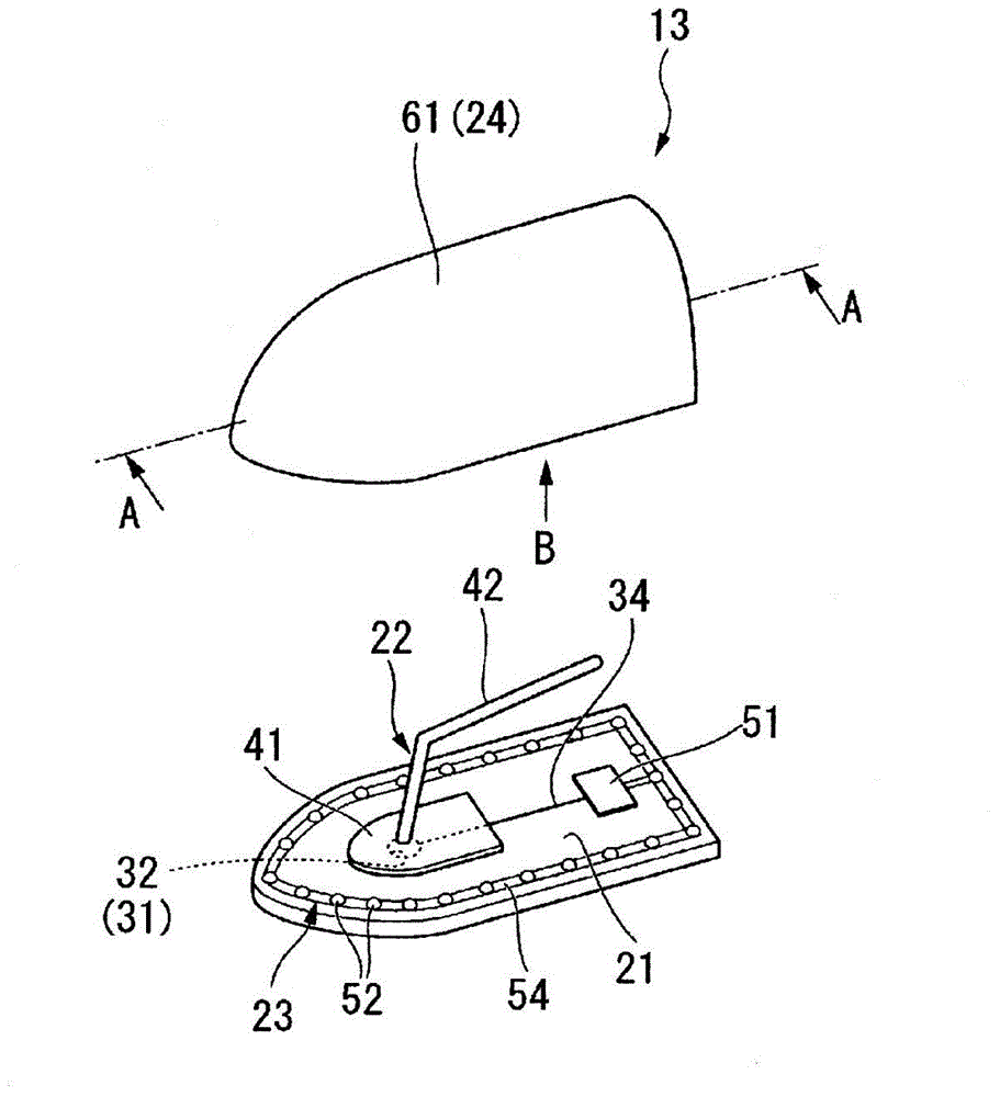
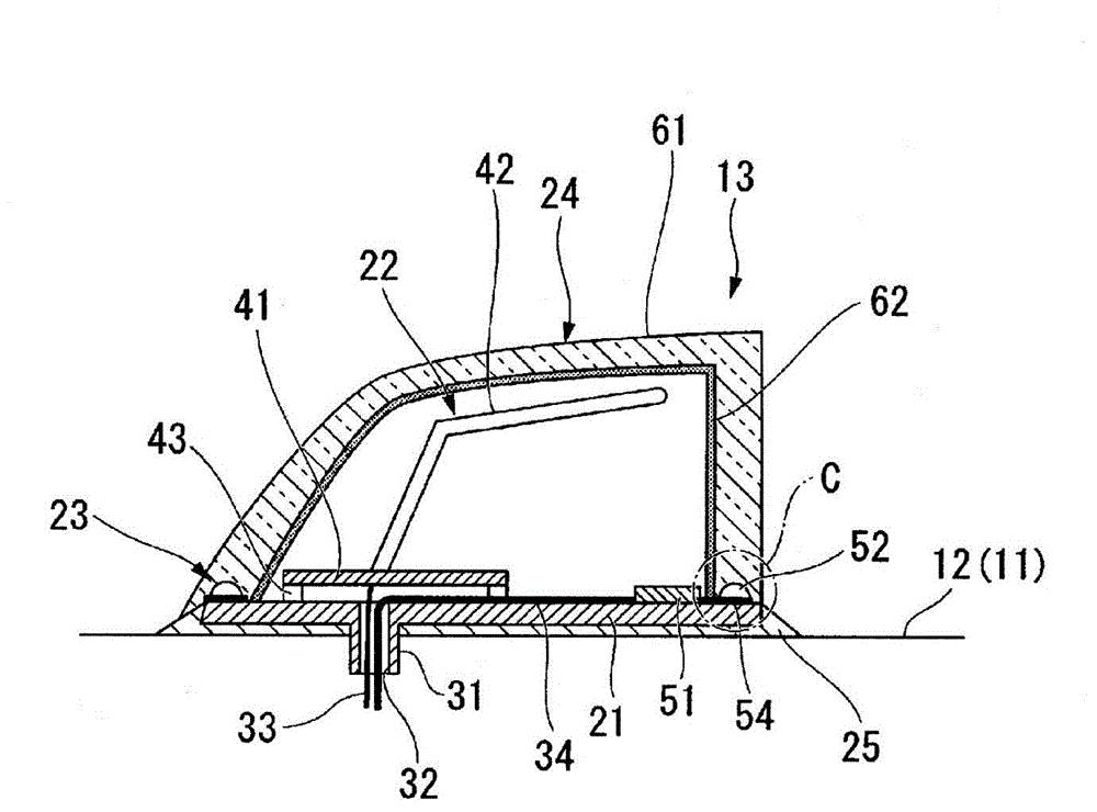
[0036] Next, embodiments of the present invention will be described based on the drawings. In this embodiment, a case where the vehicle antenna 13 with a luminous body (hereinafter simply referred to as the antenna device 13 ) of the present invention is mounted on a four-wheeled vehicle 10 will be described as an example.

[0037] (vehicle)

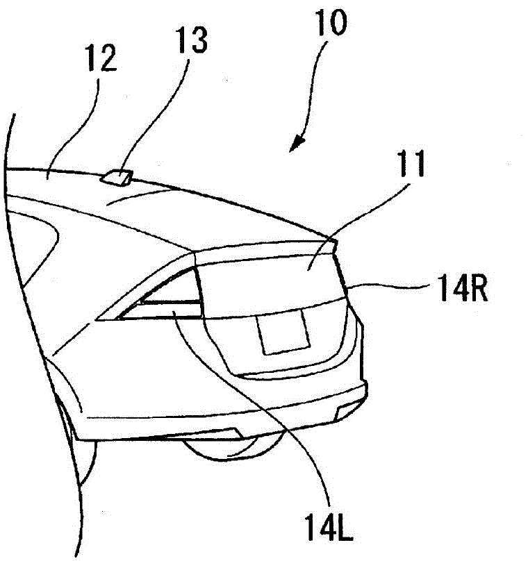
[0038] figure 1 It is a partial perspective view of the vehicle viewed from obliquely behind. It should be noted that directions such as front, rear, left, and right in the following description are assumed to be the same as the directions of the vehicle unless otherwise specified.

[0039] Such as figure 1 As shown, in the vehicle 10 of this embodiment (hereinafter also referred to as the own vehicle 10 ), the antenna device 13 is provided at the rear end portion of the roof 12 of the vehicle body 11 and at the central portion in the left-right direction.

[0040] It should be noted that, on the left and right sides of the front p...


PUM


Abstract

Provided is an antenna for a vehicle with light-emitting bodies in which the characteristics of an antenna element can be maintained and visibility can be improved. The antenna is characterized by comprising a base (21), an antenna element (42) placed on the base (21), light-emitting bodies (52) positioned lower than the antenna element (42), and a case (24) for covering and accommodating the antenna element (42) from above, the case (24) being made of a light-permeable material and the bottom end open edge of the case being placed on the peripheral edge of the base (21).

Description

technical field [0001] The invention relates to a vehicle antenna with a luminous body. Background technique [0002] Conventionally, an antenna device has been mounted on the roof of the vehicle body for reception of TV, radio, etc. In the future, research will be carried out on installing an antenna device for GPS reception on the top cover, an antenna device for receiving signals sent from the remote control key, and the like. [0003] As such an antenna device, a so-called shark fin antenna is known, which includes a fin-shaped case protruding upward from a top cover, and houses an antenna element inside the case. [0004] Here, for example, Patent Document 1 discloses a structure in which illuminants such as LEDs are mounted on the outer surface of the casing, and the illuminants are related to steering operations and remote control key operations (for example, locking and unlocking operations of door locks, for confirming large In a parking lot, etc., the turn signal...

Claims


Application Information

Patent Timeline
Patent Type & Authority Applications(China)
IPC IPC(8): B60R11/02H01Q1/22H01Q1/42
CPCH01Q1/06H01Q1/22H01Q1/3275H01Q1/42B60Q1/2611B60Q1/2661B60Q1/482H01Q1/44B60Q1/44
Inventor 矶弘树
Owner HONDA LOCK MFG CO LTD
Why Eureka
Try Eureka