
Wireless communication device

A wireless communication device and antenna technology, which is applied in the directions of image communication, TV, color TV components, etc., can solve the problems of easily damaged antenna directivity, poor radio wave receiving sensitivity, low receiving sensitivity, etc., and achieves good antenna sensitivity. , the effect of improving communication sensitivity

Inactive Publication Date: 2008-03-19
SHARP KK
View PDF7 Cites 0 Cited by
  • Summary
  • Abstract
  • Description
  • Claims
  • Application Information

AI Technical Summary

Problems solved by technology

[0007] However, in the technology described in the above-mentioned publication, although no extra space is added to the liquid crystal television device 50, no unnecessary protrusions are produced, and a portable liquid crystal television device with a simple structure can be realized. If the handle part 52 is pulled out from the main body) 51, there is a problem that the receiving sensitivity to the radio waves transmitted from the front of the display screen is not good, and in addition, the directivity of the antenna is easily affected by contact with the outside. Changeable, susceptible to breakage
However, if it is arranged inside, it is covered with an electromagnetic shielding member in order to avoid radiation, etc., so it is not conducive to receiving radio waves
In addition, inside the liquid crystal television device, as mentioned above, in addition to the electromagnetic shielding member, there are also various shields (liquid crystal panels, wiring boards, internal structural parts, etc.) that receive radio waves, so there are cases where the receiving sensitivity is low question
Therefore, it is difficult to arrange the antenna inside the device

Method used


Image

  • Wireless communication device
  • Wireless communication device
  • Wireless communication device

Examples


Embodiment Construction

[0033]Hereinafter, although an Example and a comparative example demonstrate this invention in more detail, this invention is not limited to these descriptions at all.

[0034] First, an example of a usage environment of a liquid crystal television device (wireless communication device) as an embodiment of the present invention will be described with reference to FIG. 6 .

[0035] FIG. 6 is an explanatory diagram showing an outline of a wireless AV system 1 as a display-separate wireless TV receiver. As shown in FIG. 6, a wireless AV system 1 is composed of a wireless center unit (hereinafter referred to as wireless center) 2 as a basic device, and a television (TV) main unit (hereinafter referred to as TV main unit) 3 as a portable terminal (wireless terminal). In this configuration, the wireless center 2 and the TV main body 3 (wireless communication device) form a pair to form a wireless transmission network.

[0036] As shown in FIG. 6, the TV main body 3 is a wireless un...


PUM


Abstract

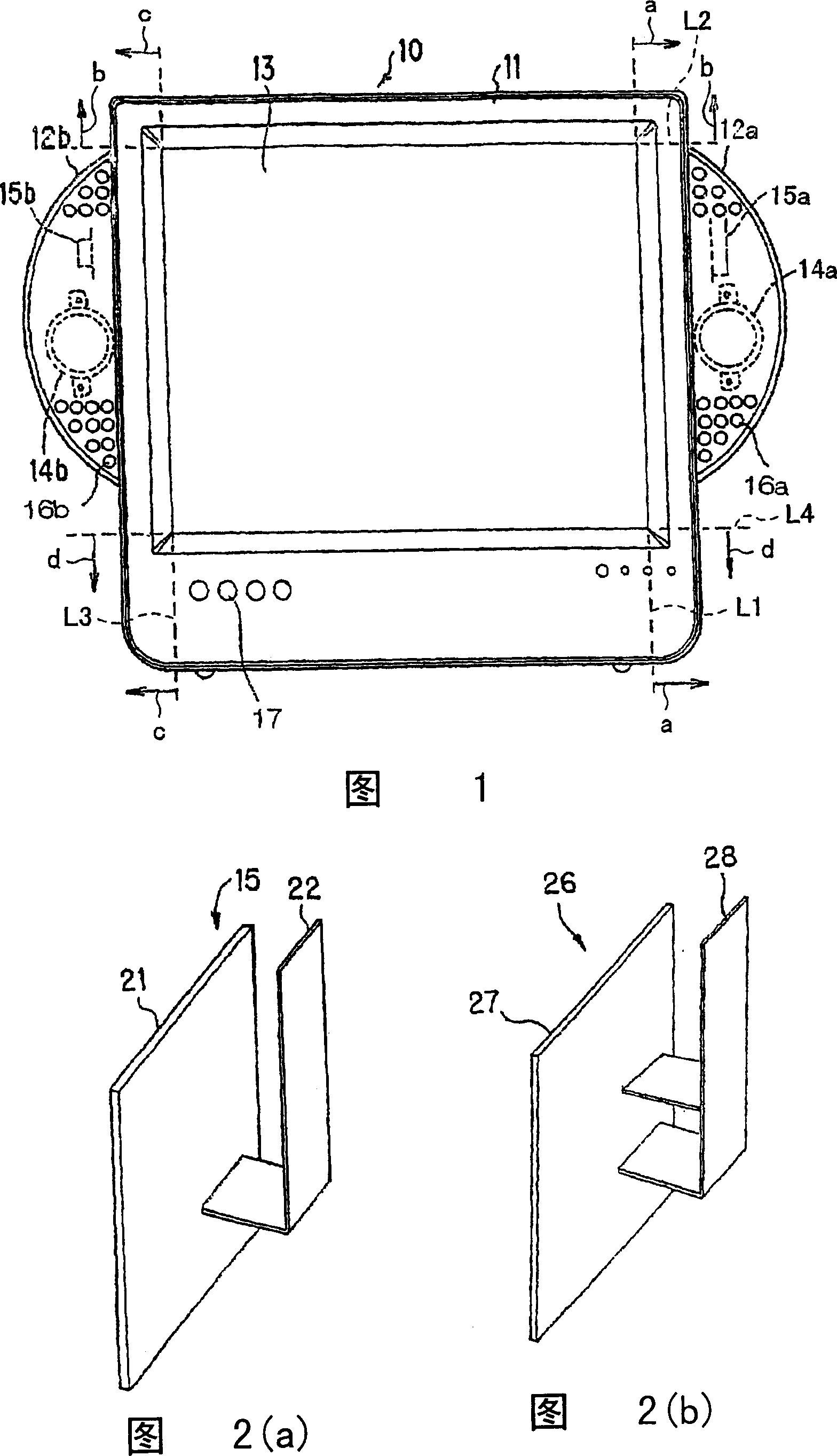
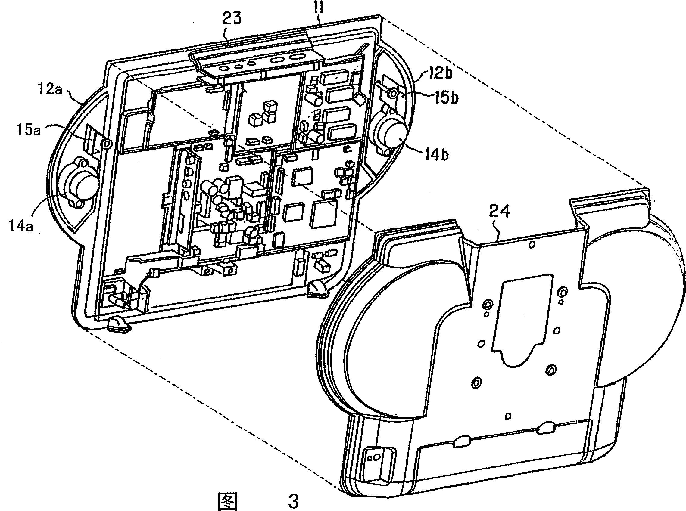
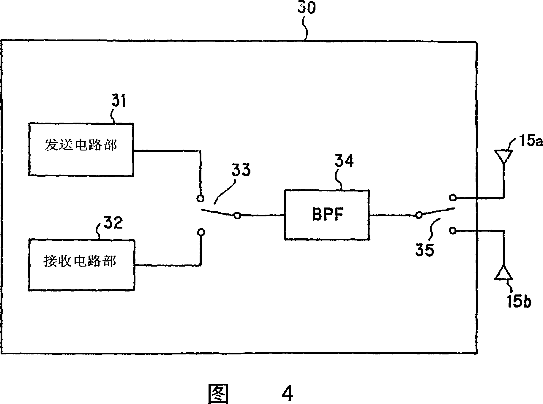
In a liquid crystal television device (10) as a wireless communication device, speaker-receiving portions (12a, 12b) are formed integrally with a body portion (11) where components such as a liquid crystal panel portion (13) etc. are received. The body portion (11) is electromagnetically shielded but not so are the speaker-receiving portions (12a, 12b). Antennas (15a, 15b) are arranged in the speaker-receiving portions (12a, 12b) together with speakers (14a, 14b) such that the installation directions of the antennas are shifted 90 degrees to each other. The wireless communication device has an antenna structure capable of improving transmission-reception sensitivity in all directions.

Description

technical field [0001] The present invention relates to a wireless communication device, which can be suitably used in portable devices such as LCD TV devices, TL TV devices, PDP TV devices, and CRT TV devices. Background technique [0002] In recent years, portable wireless communication devices such as liquid crystal televisions and CRT televisions have appeared. Among such wireless communication devices, it has been proposed to transmit and receive video signals wirelessly using SS (Spread Spectrum: Spread Spectrum) standard of IEEE.802.11 or IEEE.802.11B. In addition, in such a wireless communication device, a next-generation mobile phone device, PHS (Personal Handy-Phone System), or Bluetooth (Blue Tooth) that can be used not only for the above-mentioned wireless method but also for high-speed data transmission have also been proposed. scheme. [0003] In such a wireless communication system, a receiving antenna is necessary. In general, the antenna length of an ante...

Claims


Application Information

Patent Timeline
Patent Type & Authority Patents(China)
IPC IPC(8): H04N5/64
Inventor 畔柳均相羽立志
Owner SHARP KK
Learn More