

Cooling plug for notebook computer
A technology for notebooks and heat dissipation vents, which is applied in the direction of instruments, electrical digital data processing, digital data processing components, etc., can solve problems such as waste of heat energy, and achieve the effect of solving cold hands
Inactive Publication Date: 2015-05-20
李林
View PDF0 Cites 0 Cited by
- Summary
- Abstract
- Description
- Claims
- Application Information
AI Technical Summary
Problems solved by technology
Most of the existing notebooks dissipate the heat generated through the side cooling vents, especially in winter, when the warm air on the side of the computer is constantly blowing and the hands typing on the keyboard are exposed to the cold air, which results in a waste of heat energy
Method used
View moreImage
Smart ImageViewing Examples

Examples
Embodiment Construction
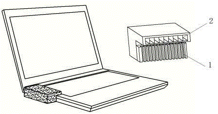
[0009] figure 1 The middle sponge plug body (1) can be inlaid with the cooling vent of the notebook, and is located at the entrance of the ventilation duct (2) and glued together; the ventilation duct (2) is a hollow cuboid, and the air outlet points to the keyboard. When in use, the sponge plug body (1) is embedded in the heat dissipation port of the notebook, hot air enters the ventilation duct (2) through the sponge plug body (1), and is discharged along the duct from the air outlet to the keyboard, providing heat for the hands.
Login to View More PUM
 Abstract
A cooling plug for a notebook computer is formed by combining a sponge plug body and a ventilating duct. The sponge plug body can be embedded in a heat dissipation port of the notebook computer, located at an inlet of the ventilating duct and bonded to the inlet of the ventilating duct. The ventilating duct is a hollow cuboid, and an air outlet of the ventilating duct faces a keyboard. When the cooling plug is in use, the sponge plug body is embedded in the heat dissipation port of the notebook computer, and hot air enters the ventilating duct through the sponge plug body and then is discharged to the keyboard part from the air outlet along the duct to provide heat for the two hands of a user.
Description
technical field [0001] The invention relates to a cooling plug for a notebook, in particular to a cooling plug for a notebook using cooling air for hand heating. Background technique [0002] The heat dissipation plug is a tool that blocks the heat dissipation port of the notebook and makes the hot air blow to the keyboard, which can solve the freezing phenomenon of fingers when typing on the keyboard in winter. Most of the existing notebooks discharge the heat generated through the side cooling vents. Especially in winter, the hands that are typing on the keyboard are exposed to the cold air while the warm air on the side of the computer is constantly blowing, resulting in a waste of heat energy. Contents of the invention [0003] In order to solve such a conventional problem, the present invention provides a notebook cooling plug. It is composed of two parts, the sponge plug body and the ventilation duct. The sponge plug body is embedded in the cooling vent of the note...
Claims
Login to View More Application Information
Patent Timeline
 Patent Type & AuthorityApplications(China)
IPC IPC(8): G06F1/20
CPCG06F1/203
Inventor不公告发明人
Owner李林