Method and device for raising trigger speed and locking force of speed locking device

A speed locking and locking device technology, applied to bridge parts, bridges, building components, etc., can solve the problems of slow trigger locking speed, not too large volume, high production cost, etc., to achieve improved trigger locking speed, strong applicability, and production low cost effect

Active Publication Date: 2015-06-10
GUIZHOU TRANSPORTATION PLANNING SURVEY & DESIGN ACADEME
View PDF5 Cites 8 Cited by
  • Summary
  • Abstract
  • Description
  • Claims
  • Application Information

AI Technical Summary

Problems solved by technology

However, due to the limitation of the installation position of the commonly used speed locker at present, the volume of the designed product should not be too large. The use method of the...

Method used


Image

  • Method and device for raising trigger speed and locking force of speed locking device
  • Method and device for raising trigger speed and locking force of speed locking device
  • Method and device for raising trigger speed and locking force of speed locking device

Examples


Embodiment Construction

[0013] The present invention will be further described below in conjunction with the accompanying drawings and embodiments.

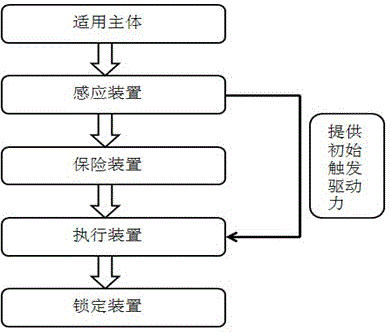
[0014] Embodiments of the present invention: when implementing a method of improving the triggering speed and locking force of the speed locker of the present invention, as figure 1 As shown, the method is to first make an applicable body composed of a fixed body and a sliding body (the fixed body and the sliding body can be made according to actual installation requirements), and an induction device composed of a speed locker (the speed locker can use existing market finished product of speed locker for sale), safety device (safety device can adopt conventional safety buckle, safety pin and other devices), actuator linked with induction device, locking device with interlocking tooth block; The body undergoes relative displacement under the vibration of the building, and the sensing device senses the relative moving speed of the applicable body. When t...


PUM


Abstract

The invention discloses a method and device for raising the trigger speed and the locking force of a speed locking device. The device comprises an applicable main body consisting of a fixed body and a sliding body, an induction device consisting of the speed locking device, a safety device, an executing device which is in linkage with the induction device, and a locking device provided with mutually locked tooth blocks. The method comprises the following steps: the fixed body and the sliding body of the applicable main body generate relative displacement under the shaking of a building; the induction device perceives the relative moving speed of the applicable main body; when the shaking is so large that the moving speed exceeds a set value, the induction device breaks the safety device and provides initial trigger driving force to push the executing device to execute mechanical locking; the executing device relieves the suppression on the locking device, the tooth blocks of the locking device are meshed, and the mechanical self-locking of the locking device in the relative slippage direction of the applicable main body is realized. The device disclosed by the invention has the advantages of being simple and reliable, being high in applicability, being high in trigger locking speed, being great in locking force, and being lower in production cost.

Description

technical field [0001] The invention relates to a method and a device for increasing the triggering speed and locking force of a speed locker, belonging to the technical field of structural protection. Background technique [0002] Speed ​​lockers are commonly used in engineering structures such as bridges and houses. It is a piston-type cylindrical cavity structure. Through the action of high-viscosity fluid filled in the cavity, the resistance generated between the cylinder and the piston at low speed is very small, and the resistance increases rapidly as the speed increases. As high as the design value, the functions of relative displacement at low speed and low speed at high speed between the connecting members at both ends are realized. However, due to the limitation of the installation position of the commonly used speed locker at present, the volume of the designed product should not be too large. The use method of the speed locker in conjunction with the conventiona...

Claims


Application Information

Patent Timeline
IPC IPC(8): E01D19/00E04B1/98
CPCE01D19/00E04B1/98
Inventor 杜镔刘建军龙万学唐璐宁响亮刘军杨鸿波万麟韦定超杨健饶毅刚余洋李银斌陈冠桦邓晓红
Owner GUIZHOU TRANSPORTATION PLANNING SURVEY & DESIGN ACADEME
Why Eureka
Try Eureka