Micro double balanced mixer

A technology of double-balanced mixer and frequency-mixing diode, which is applied to the balance device of modulation and conversion, etc., can solve the problems of large area and volume of passive components, and achieve good isolation of local oscillator, small size, and reduced size. Effect

Active Publication Date: 2015-06-10
庄昆杰
View PDF6 Cites 1 Cited by
  • Summary
  • Abstract
  • Description
  • Claims
  • Application Information

AI Technical Summary

Problems solved by technology

[0003] Most of the existing double-balanced mixers are diode double-balanced mixers or CMOS double-balanced mixers. For the schematic diagram of diode double-balanced mixers, see figure 1 As shown, it is generally made by thick film technology, and the passive components occupy a large area and are bulky, so they are not suitable for miniaturized microwave radio frequency circuits in the field of mobile communications.

Method used


Image

  • Micro double balanced mixer
  • Micro double balanced mixer
  • Micro double balanced mixer

Examples


Embodiment 1

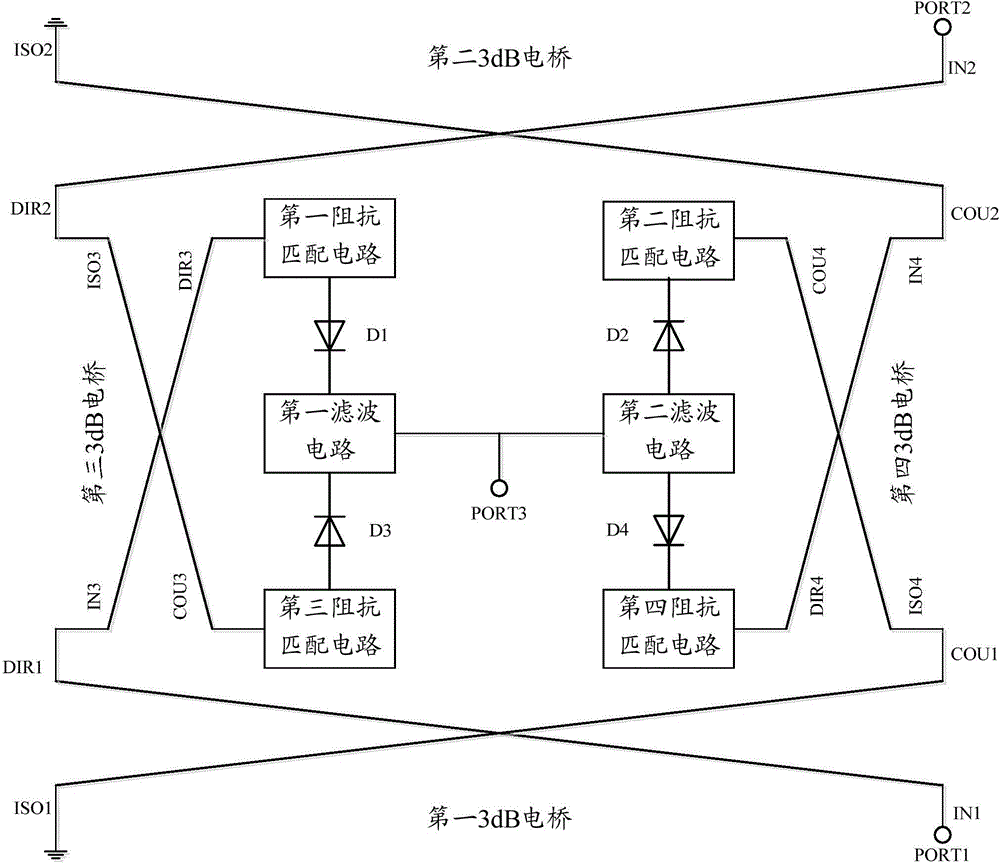
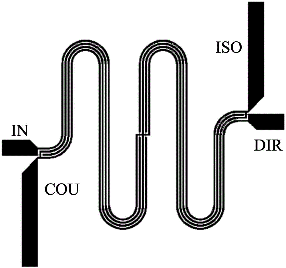
[0042] In the first embodiment, the first pin of the first mixing diode D1 is an anode, and the second pin is a cathode, and the first pin of the fourth mixing diode D4 is a cathode, and the second pin is an anode. For details, see Figure 4 As shown, the first impedance matching circuit includes a first capacitor C1 and a first inductor L1, one end of the first capacitor C1 is connected to the direct terminal DIR3 of the third 3dB bridge, and the other end is connected to the first pin of the first mixing diode D1 (ie, the anode); one end of the first inductor L1 is connected to the first pin (ie, the anode) of the first mixing diode D1 , and the other end is grounded. The second impedance matching circuit includes a second capacitor C2 and a second inductor L2, one end of the second capacitor C2 is connected to the coupling terminal COU4 of the fourth 3dB bridge, and the other end is connected to the cathode of the second mixing diode D2; the second inductor L2 One end of D...

Embodiment 2

[0060] In the second embodiment, the first pin of the first mixing diode D1 is a cathode, and the second pin is an anode, and the first pin of the fourth mixing diode D4 is an anode, and the second pin is a cathode. The structures of the impedance matching circuit and the filter circuit of the miniaturized double-balanced mixer provided in the second embodiment are the same as those provided in the first embodiment, and will not be repeated here. The circuit diagram and structural layout of the miniaturized double-balanced mixer can be found in Figure 8 and Figure 9 .

[0061] The miniaturized double-balanced mixer provided in Embodiment 2 can be used to realize down-conversion, and change the input frequency to 1.5 MHz or 90 MHz. Specifically, the first 3dB bridge and the second 3dB bridge respectively divide the RF input signal and the LO input signal into two paths, which are used as the input of the third 3dB bridge and the fourth 3dB bridge, and the signals of the two...


PUM

PropertyMeasurementUnit
Thicknessaaaaaaaaaa
Thicknessaaaaaaaaaa

Abstract

The invention discloses a micro double balanced mixer. The micro double balanced mixer comprises a first 3dB electric bridge, a second 3dB electric bridge, a third 3dB electric bridge, a fourth 3dB electric bridge, a first impedance matching circuit, a second impedance matching circuit, a third impedance matching circuit, a fourth impedance matching circuit, a first mixer diode, a second mixer diode, a third mixer diode, a fourth mixer diode, a first filter circuit and a second filter circuit, wherein a public node between the first filter circuit and the second filter circuit is a transmission signal port. The micro double balanced mixer is high in local oscillator power, good in local oscillator isolation, large in dynamic range, small in variable-frequency loss, small in size dimension and suitable for a small-sized microwave radio frequency circuit, and has an inhibiting effect on even-order products of RF (radio frequency).

Description

technical field [0001] The invention relates to the technical field of mixers in the communication field, in particular to a miniaturized double-balanced mixer. Background technique [0002] A mixer is an integral part of an RF microwave circuit system. Whether it is microwave communication, radar, remote control, remote sensing, or reconnaissance and electronic countermeasures, as well as microwave measurement systems, microwave signals must be processed by reducing the frequency to medium and low frequencies with a mixer. In practice, most AM (Amplitude Modulation, amplitude modulation), SSB (Single Side Band, single sideband) and digital transmitters require a mixer to convert the signal frequency to a higher frequency, and then transmit it into the air ; while the superheterodyne receiver needs to use the mixer to convert the frequency of the received signal to a lower frequency - intermediate frequency. The receiver must use this lower frequency signal, because the si...

Claims


Application Information

Patent Timeline
IPC IPC(8): H03D7/14
Inventor 庄昆杰
Owner 庄昆杰
Why Eureka
Try Eureka