Eureka AIR delivers breakthrough ideas for toughest innovation challenges, trusted by R&D personnel around the world.

A steam atomizing nozzle

A technology of atomizing nozzles and steam, applied in the direction of spraying devices, liquid spraying devices, spraying devices with movable outlets, etc., which can solve the problems of easy safety accidents and low safety and reliability, so as to improve the atomization effect and avoid impact Effect

Active Publication Date: 2018-10-30
CHENGDU ZHIRONG ZHICHUANG INTPROP MANAGEMENT CO LTD
View PDF6 Cites 0 Cited by
  • Summary
  • Abstract
  • Description
  • Claims
  • Application Information

AI Technical Summary

Problems solved by technology

In the prior art, a straight nozzle is usually used, and the liquid obtains greater kinetic energy after being pressurized. After passing through the nozzle, the liquid will be ejected at a high speed. Under the interaction of the surface tension, viscosity and air resistance of the liquid, the liquid will The dripping, smooth flow, and wavy flow gradually change to the spray flow, and finally realize the two-phase separation of gas and liquid; but because the water flow discharged from the direct injection nozzle has surface tension, it needs to continuously flow downhole during the process of the liquid turning into a spray flow. Only by pressurizing can the liquid be ejected at a high speed and rub against the surrounding air to separate and atomize, and the higher the downhole air pressure, the lower the safety and reliability faced during gas production, which can easily lead to safety accidents

Method used


Image

  • A steam atomizing nozzle
  • A steam atomizing nozzle
  • A steam atomizing nozzle

Examples


Embodiment 1

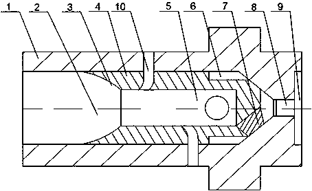
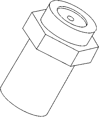
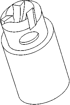
[0022] Such as Figure 1~3 As shown, this embodiment includes a nozzle core 4 and a nozzle shell 1 sleeved outside the nozzle core 4. The end of the nozzle shell 1 is provided with a spray hole 8, and an inner conical surface is set at one end of the nozzle core 4. 3, and the inner conical surface 3 and the inner wall of the nozzle shell 1 form an air intake cavity 2, and the other end of the nozzle inner core 4 has a through hole facing the jet flow hole 8, and a plurality of swirls are installed on the inner wall of the through hole The blade 7, and the through hole and the inner wall of the nozzle inner core 4 form a swirl cavity 5; it also includes two air holes 10 that pass through the nozzle shell 1 and the nozzle inner core 4, and the two air holes 10 are arranged alternately on the axis of the nozzle inner core 4 Both sides, and the gas outlet end of the air hole 10 is bent in the opposite direction of the gas-liquid two-phase flow in the nozzle inner core 4 .

[0023...


PUM


Abstract

The invention discloses a steam atomizer. The atomizer comprises nozzle inner core and a nozzle shell, wherein the end part of the nozzle shell is provided with a jet nozzle, one end of the nozzle inner core is provided with an inner circular conical surface, and the other end of the nozzle inner core is provided with a through hole dead against the jet hole; an air inlet cavity is formed by the inner circular conical surface and the inner wall of the nozzle shell, a plurality of swirl blades are arranged on the inner wall of the through hole, and a swirl cavity is formed by the through hole and the inner wall of the nozzle inner core; an annular convective tank is arranged in the middle of the nozzle inner core, and two air holes are symmetrically formed in the two ends of the convective tank. When a gas-liquid two-phase mixture in a gas well is pushed to ascend by pressure in the well, the gas-liquid mixture enters the air inlet cavity and is subjected to volume compression by the inner circular conical surface, so as to improve the flow velocity of the gas-liquid mixture; when the gas-liquid mixture enters the swirl cavity, the liquid is mutually in contact with the swirl blade, fluid is driven to rotate by the swirl blade, and finally the gas-liquid mixture is thrown out of the jet hole by the centrifugal force generated by rotation.

Description

technical field [0001] The invention relates to the field of downhole gas recovery, in particular to a steam atomizing nozzle. Background technique [0002] In most gas wells in China, there will be water accumulation at the bottom of the well to varying degrees. For gas wells with bottom water or edge water, the liquid-gas ratio will gradually increase during the production process. If the liquid-gas ratio or bottom-hole liquid accumulation is not adjusted in time If the wellhead is not removed in time, it will lead to the normal production of the gas well, or even drown the gas well and cause production shutdown. Therefore, correctly predict the lifting capacity of the gas well at different levels of liquid content and choose the appropriate drainage and gas recovery process for the gas well according to the actual situation of the gas well. has important practical significance. [0003] At the beginning of a small amount of liquid accumulation at the bottom of the gas we...

Claims


Application Information

Patent Timeline
Patent Type & Authority Patents(China)
IPC IPC(8): B05B7/04B05B3/10E21B43/16
CPCB05B7/0416B05B7/10E21B43/16
Inventor 谭正怀
Owner CHENGDU ZHIRONG ZHICHUANG INTPROP MANAGEMENT CO LTD
Why Eureka
Eureka Blog
Learn More