
Method for controlling thickness of optical remote sensor space truss rod adhesive glue layer

A technology of optical remote sensors and space trusses, which is applied in the direction of material gluing, connecting components, mechanical equipment, etc., and can solve the problems of inconsistent adhesive layer thickness and thickness uniformity, low reliability of optical remote sensors, waste of raw materials and aerospace resources, etc. problems, achieve the effect of shortening the development cycle, reducing development and launch costs, and ensuring the bonding strength requirements

Active Publication Date: 2015-08-12
CHANGCHUN INST OF OPTICS FINE MECHANICS & PHYSICS CHINESE ACAD OF SCI
View PDF5 Cites 7 Cited by
  • Summary
  • Abstract
  • Description
  • Claims
  • Application Information

AI Technical Summary

Problems solved by technology

[0003] The purpose of the present invention is to propose a structure and method for controlling the thickness of the adhesive layer of the space truss bar of the optical remote sensor, to solve the problems of the thickness of the adhesive layer and the uniformity of the thickness of the adhesive layer in the prior art, and to solve the problem of the inconsistency of the thickness of the adhesive layer and the uniformity of the thickness of the raw materials and space resources. Waste, the problem of low reliability of optical remote sensors

Method used


Image

  • Method for controlling thickness of optical remote sensor space truss rod adhesive glue layer
  • Method for controlling thickness of optical remote sensor space truss rod adhesive glue layer
  • Method for controlling thickness of optical remote sensor space truss rod adhesive glue layer

Examples


Embodiment Construction

[0019] Embodiments of the present invention will be further described below in conjunction with the accompanying drawings.

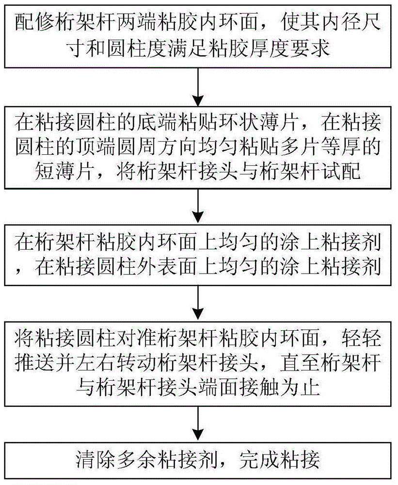
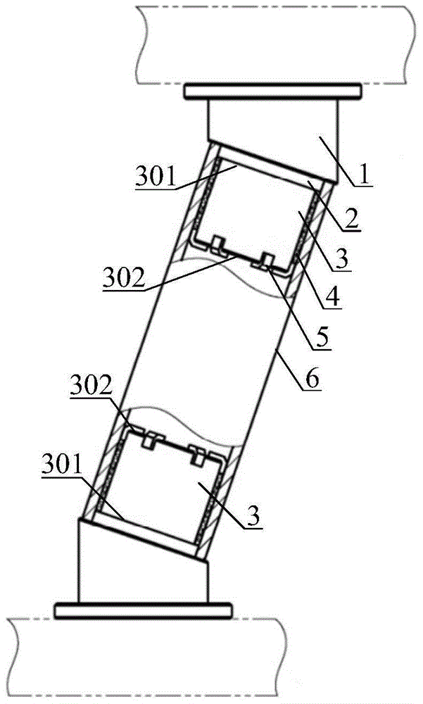
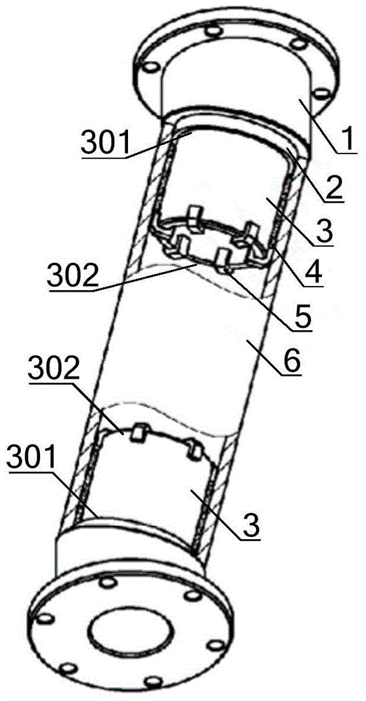
[0020] See attached figure 1 , attached figure 2 And attached image 3 A method for controlling the thickness of the adhesive layer of the space truss bar of the optical remote sensor of the present invention comprises the following steps:

[0021] Step 1: Repair the inner ring surface of both ends of the truss rod 6 with glue, so that the inner diameter and cylindricity meet the glue thickness requirements;

[0022] Step 2: Paste the ring-shaped sheet 2 on the bottom end 301 of the bonding cylinder 3, and evenly paste multiple short sheets 5 of equal thickness in the circumferential direction on the top 302 of the bonding cylinder 3, and test match the truss rod joint 1 with the truss rod 6 , until the truss rod joint 1 can smoothly rotate one circle at a uniform speed in the truss rod 6 without shaking;

[0023] Step 3: Apply adhesive 4 evenly on ...


PUM


Abstract

The invention provides a method for controlling thickness of an optical remote sensor space truss rod adhesive glue layer, and belongs to the field of space optical remote sensor space truss structure integration. The method comprises the following steps that adhesive glue internal annular surfaces of the two ends of a truss rod are configured and trimmed so that the size of internal diameter and cylindricity are enabled to meet the requirement of thickness of adhesive glue; an annular thin sheet is adhered at the bottom end of an adhesive cylinder, multiple equal-thickness short thin sheets are evenly adhered at the top end of the adhesive cylinder in a circumferential direction, and a truss rod connector and the truss rod are matched until the truss rod connector can smoothly rotate a circle at constant speed in the truss rod without waggling; an adhesive agent is uniformly coated on the adhesive glue internal annular surfaces of the truss rod, and the adhesive agent is uniformly coated on the external surface of the adhesive cylinder so that thickness of the adhesive agent of both parts is enabled to be greater than 2 / 3 of the required adhesive thickness; the adhesive cylinder is aligned with the adhesive glue internal annular surfaces of the truss rod, and the truss rod connector is slightly pushed and leftward and rightward rotated until the truss rod and the end surface of the truss rod connector are contacted; and the residual adhesive agent is removed so that adhesion is completed.

Description

technical field [0001] The invention belongs to the field of spatial optical remote sensor space truss structure integration, and in particular relates to a method for controlling the thickness of the bonding adhesive layer of the optical remote sensor space truss rods. Background technique [0002] At present, with the increasing demand for ground reconnaissance and mapping, the volume of space optical remote sensors is also increasing. In order to meet the increasingly urgent demand for lightweight, carbon fiber is widely used in aerospace work due to its high strength, high modulus and low density. Favored by researchers, the space truss structure with carbon fiber truss rods as the main load-bearing components has become the mainstream structure of large-volume space optical remote sensors. Therefore, the integration method of space truss structures has become a key technology. In order to meet the high reliability requirements of optical remote sensors, the thickness an...

Claims


Application Information

Patent Timeline
Patent Type & Authority Applications(China)
IPC IPC(8): F16B11/00
CPCF16B11/006
Inventor 杨会生李志来杨利伟袁野庞新源
Owner CHANGCHUN INST OF OPTICS FINE MECHANICS & PHYSICS CHINESE ACAD OF SCI
Learn More