Container for washing, sterilization, transportation and sterile storage of articles

A container and article technology, applied in transportation and packaging, disinfection, containers, etc., can solve the problems of limited storage and difficult stacking of containers

Active Publication Date: 2015-08-12
SAJKAN LTD
14 Cites 3 Cited by

AI-Extracted Technical Summary

Problems solved by technology

Storage of such containers may also be limited as the container...

Method used

[0050] After the items or instruments have been used, they can be returned to the frame, and the frame and the items contained therein can be placed in a sleeve to assemble the container in a first configuration for transport, thus reducing the risk of infection due to exposure risk and minimize the risk of instrument damage due to improper handling. The frame and items contained therein can be removed from the sleeve and the assembly washed, such as in an automatic washing machine, without removing the items from the frame. The sleeve and frame can be reassembled in the first configuration for sterilization of the contents of the frame and subsequent aseptic storage.
[0060] As shown in FIG. 2, the container 10, 1000 may be freestanding in any orientation. Accordingly, one or more containers 10, 1000 according to the present disclosure may be stacked and stored in a variety of configurations. The container 10, 1000 can be erected or stored on the bottom plate 24, as shown in FIG. 2(a). The container 10, 1000 can be erected or stored on the top plate 22, as shown in Fig. 2(b). The container 10, 1000 can be erected or stored on the first side panel 26, as shown in FIG. 2(c). The container 10, 1000 can be erected or stored on the second side panel 28, as shown in FIG. 2(d). The container 10, 1000 can be erected or stored at the front end 40 of the sleeve 16, as shown in Fig. 2(e). The container 10, 1000 can be erected or stored at the rear end 42 of the sleeve 16, as shown in Figure 2(f). As shown in Figures 2(g) and 2(h) and described below, the containers 10, 1000 can be stacked when stored or in a sterilization chamber, forming a gap 2001 between adjacent containers 10, 1000 to allow for the sterilization process. This facilitates the removal of air, the removal of condensate and the penetration of steam.
[0092] In one embodiment, the sleeve 1016 includes one or more recesses 9009 in the front interface 48 of the sleeve 1016 for receiving protrusions 9011 provided in the front wall 32 of the frame 1012. As shown in FIGS. 9( i ) and 9( j ), protrusion 9011 may include one or more tongues extending laterally from front wall 1032 of frame 1012 toward second region 1082 of sleeve 1016 . Corresponding recesses 9009 engage protrusions 9011 to ensure proper alignment and engagement of front wall 32 , front interface 48 and front seal 50 .
[0121] The second region 282 includes a portion 292 comprised of a metallic material, such as aluminum. In one embodiment, portion 292 includes a portion of each of top panel 222 , bottom panel 224 , first side panel 226 , and second side panel 228 that are constructed of metal. In one embodiment, portion 292 is relatively centered in second region 282 . Metal portion 292 stores heat during the sterilization phase of the sterilization process and then releases the stored heat to facilitate drying of the contents of sterilization chamber 218 during the drying phase of the sterilization process.
[0124] FIGS. 21 to 24 illustrate alternative embodiments of a frame according to the present disclosure. 21 and 22 illustrate the frame 312 adapted to receive the basket 320 . Frame 312 may also receive...

Abstract

A container for washing, sterilization, transportation and sterile storage of articles for sterilization is provided. The container includes a sleeve and a frame adapted to receive articles for sterilization. The container includes at least one filtered opening to permit communication between the sterilization apparatus and the sterilization chamber for the communication of steam and air. In a first configuration, a front and rear wall of the frame engage the sleeve to create a sterilization chamber. The container may be stacked and stored in any orientation. In a second configuration, the frame rests or nests on top of the sleeve to permit access to and use of the sterilized articles. The container, may include one or a plurality of openings for communication between a sterilization apparatus and the sterilization chamber and one or more filters adjacent to the pluralities of openings.

Application Domain

Surgical furnitureLavatory sanitory +4

Technology Topic

EngineeringMechanical engineering

Image

  • Container for washing, sterilization, transportation and sterile storage of articles
  • Container for washing, sterilization, transportation and sterile storage of articles
  • Container for washing, sterilization, transportation and sterile storage of articles

Examples

  • Experimental program(1)

Example Embodiment

[0046] In the following description, where appropriate, similar features in the drawings are given the same reference numerals. Terms such as "front" and "rear", "top" and "bottom", "first" and "second", "right" and "left" can be used to identify opposite ends of structures or different configurations. This terminology is used for illustrative purposes and is not intended to limit the present disclosure.
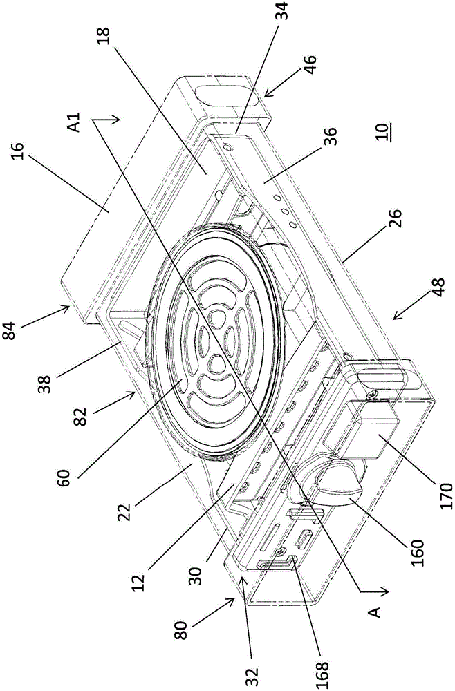
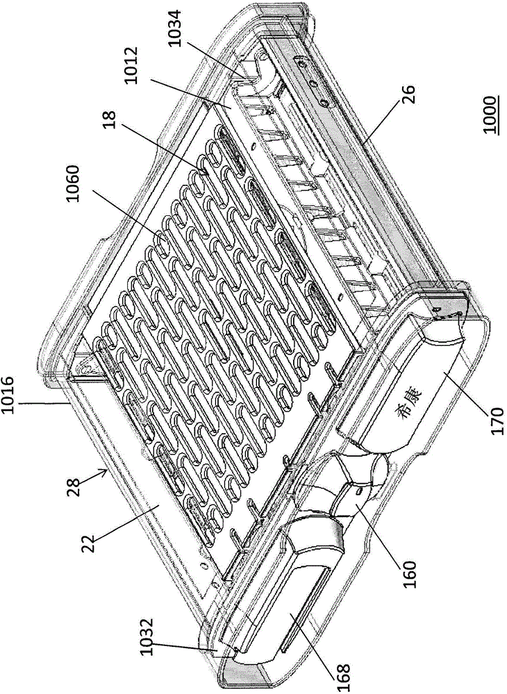
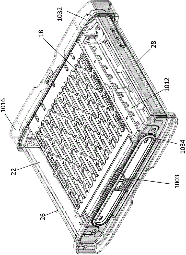
[0047] One embodiment of the present disclosure provides a container assembly that contains items to be sterilized, such as medical and dental instruments. The components of the assembly can be placed in the washing equipment to wash the instrument and remove debris before the disinfection process. One or more containers can be placed in a sterilization device, such as an autoclave or a box sterilization device such as STATIM TM , Used to sterilize the contents of the container. The container also allows for aseptic storage and transportation of the instrument, and provides improved access to the instrument during use. The container includes a sleeve and a frame adapted to receive the items to be sterilized. The sleeve has a top plate, a bottom plate and two side plates, which define a cavity for receiving the frame. The sleeve and the frame are engaged to form a sterilization chamber. In one embodiment, the sleeve and the frame are in sealing engagement. In another embodiment, the curved path is configured at the engagement between the frame and the sleeve. The container includes at least one opening that allows communication between the sterilization device and the sterilization chamber, for example for communicating steam. In one embodiment, the container includes a plurality of openings for communication between the sterilization device and the sterilization chamber, and one or more filters adjacent to the plurality of openings.
[0048] In one embodiment, the container has two configurations. In the first configuration, the frame is housed in the sleeve, and the front and rear walls of the frame engage the sleeve to form a sterilization chamber. In one embodiment, the front wall and the rear wall are adapted to be connected to opposite ends of the tray, box or basket, and they are configured to be seated in a suitably sized sleeve of the container. In another embodiment, the frame includes a front wall, a rear wall, and first and second side walls, which are adapted to receive items to be sterilized, as described herein. The frame can be inserted or slid into the sleeve to assemble the container in the first configuration. In the first configuration, the container and the items contained therein can be sterilized and efficiently stored by placing and stacking multiple containers vertically in any direction. The sterile items contained in the container in the first configuration can be kept in the container and transported to the place of use.
[0049] In the second configuration, the frame abuts or nests on the sleeve to allow access and use of sterilized items. After sterilization, or after removing the sterilized container from storage, the aseptic seal can be broken at the place of use, such as in the presence of a medical or dental patient, and the frame and the items contained therein can be removed from the sleeve. For example, the frame and the items contained in it can be moved out of the sleeve by sliding the frame out of the sleeve. The size of the frame is set to abut on the top or bottom plate of the sleeve. In one embodiment, the frame is nested or partially nested in the top or bottom plate of the sleeve. The second configuration allows the use of containers and items with a minimum area or footprint, because the frame can rest on the sleeve and the sleeve does not need to be stored elsewhere.
[0050] After using the items or instruments, they can be returned to the frame, and the frame and the items contained in it can be put into the sleeve, and the container can be assembled in the first configuration for transportation, thus reducing the risk of infection due to exposure and saving The risk of instrument damage due to improper operation is minimized. The frame and the items contained therein can be removed from the sleeve and the components can be washed, for example in an automatic washing machine, without removing the items from the frame. The sleeve and frame can be reassembled in the first configuration in order to sterilize the items in the frame and sterile storage behind.
[0051] In some embodiments, the sleeve or at least a portion of the sleeve includes a transparent material so that the contents or stored items in the container can be seen. In other embodiments, a mechanism is provided to indicate whether the container has undergone a sterilization cycle and is maintained in a sterile state or whether it has been taken and placed.
[0052] Figures 1 (a), (b) and (c) illustrate an embodiment of a container 10, 1000 according to the present disclosure. The container 10, 1000 includes a frame 12 and a sleeve 16. The container 10, 1000 is shown as the first configuration, where the frame 12 is contained in the sleeve 16. The sleeve 16 engages with the frame 12 to form a sterilization chamber 18.
[0053] Such as Figure 1(a) to Figure 1(c) with figure 2 As shown in, the sleeve 16 includes a top plate 22, a bottom plate 24, a first side plate 26 and a second side plate 28. The top plate 22, the bottom plate 24, the first side plate 26 and the second side plate 28 define a cavity 30 for receiving and accommodating the frame 12. In one embodiment, the current state of the chamber 30 is substantially rectangular. The sleeve 16 may be constructed from one or more individual plates, or as one piece.
[0054] In one embodiment, the frame 12 includes at least a front wall 32 and a rear wall 34, which are adapted to receive or contain items to be sterilized. In one embodiment (not shown), the front wall 32 and the rear wall 34 can be connected or attached to an existing sterilization box or basket, which is of suitable size and configured with an opening for the insertion of the sleeve Sterilize the instruments contained in the cartridge 16 while in. In another embodiment (not shown), the front wall 32 and the rear wall 34 can be connected or attached to an existing sterilization box, which can be inserted into a suitable size sleeve (not shown). In yet another embodiment, the frame 12 includes a front wall 32, a rear wall 34 and a first side wall 36 and a second side wall 38. The frame 12 is configured or adapted to receive items to be sterilized, as described in further detail below.
[0055] Such as Figure 3(a) , 3(b) As illustrated in 4(a), the frame 12 and the sleeve 16 are in sealing engagement to define the sterilization chamber 18. In one embodiment, the frame 12 slides through the front end 40 of the sleeve 16 to the rear end 42 of the sleeve 16. The rear interface 46 at the rear end 42 of the sleeve 16 engages the rear wall 34 of the frame 12. The front interface 48 at the front end 40 of the sleeve 16 engages the front wall 32 of the frame 12. In one embodiment, when the frame 12 slides into the sleeve 16, the rear wall 34 of the frame 12 first sealingly engages the rear interface 46 of the sleeve 16, and then the front wall 32 of the frame 12 engages the front interface 48 of the sleeve 16. In another embodiment, when the frame 12 slides into the sleeve 16, the front wall 32 of the frame 12 first engages the front interface 48 of the sleeve 16, and then the rear wall 34 of the frame 12 sealingly engages the rear interface 46 of the sleeve 16. .
[0056] The dimensions of the containers 10, 1000 and the sleeve and frame assembly can vary, as described below. In some embodiments, the sides of the container and its frame and sleeve assembly are longer than the widths of the front and rear ends, and the frame is inserted and extended in the length direction through the sleeve, as shown in Figure 1(a). In other embodiments, the sides of the container and its frame and sleeve assembly are shorter than the width of the front and rear ends, and the frame is inserted and extends through the sleeve in the width direction, as shown in Figure 1(b) and (c) .
[0057] The container 10, 1000 may include a front seal 50 and a rear seal 52 at the respective front and rear interfaces 48, 46, or one or more curved paths at the front and rear interfaces 48, 46, or a seal and curved path configuration combination. A tortuous path refers to a meandering or turning path in which the corners in the path inhibit the entry and travel of bacteria into the container 10, 1000 and the sterilization chamber 18. The curved path can be formed between the front wall 32 of the frame 12 and the front interface 48 of the sleeve 16 by providing, for example, many complementary protrusions and/or depressions on the mating surface of the front wall 32 and the front interface 48, as in At least illustrated in Figure 3(b). Similarly, the curved path can be formed between the rear wall 34 of the frame 12 and the rear interface 46 of the sleeve 16 by providing, for example, many complementary protrusions and/or depressions on the mating surface of the rear wall 34 and the rear interface 46 . One or more tortuous paths between the front wall 32 and the front interface 48 and between the rear wall 34 and the rear interface 46 inhibit bacteria from entering the container 10 and the sterilization chamber 18.
[0058] In one embodiment, the container 10, 1000 includes at least one opening for communication between the sterilization device and the sterilization chamber 18. In another embodiment, the container 10, 1000 includes multiple openings, such as multiple openings in one of the plates of the sleeve 16. In the embodiment in FIGS. 1( a )-(c) and 2, the container 10 includes a plurality of openings 60 in the top plate 22 and a plurality of openings 62 in the bottom plate 24. A plurality of openings 60, 62 allows communication between the sterilization device and the sterilization chamber 18, as described in detail below. One or more filter fittings 70, also described in further detail below, may be provided adjacent to the plurality of openings 60, 62. In some embodiments, multiple openings 60 may be in the side plate 26 and multiple openings 62 may be in the side plate 28.
[0059] To assemble one embodiment of the container 10, 1000 for sterilization in the first configuration, the article is placed in the frame 12 and the frame 12 is inserted into the cavity 30 of the sleeve 16. The frame 12 and the sleeve 16 are engaged to form a sterilization chamber 18. The container 10, 1000 may be placed in a sterilization device, and the steam cycle for sterilization and the air used to dry the contents of the container 10 pass through the filter assembly 70 and one or more openings 60, 62. After sterilization, the container 10 can be removed from the sterilization equipment and stored, which provides for aseptic storage of items in the containers 10, 1000. In one embodiment, the container 1000 includes a rear handle 1003, which can be used with a knob 160 provided on the front wall 32 of the frame 12 to transport the container 1000 when the container is hot.
[0060] Such as figure 2 As shown in, the containers 10, 1000 can be free-standing in any direction. Therefore, one or more containers 10, 1000 according to the present disclosure can be stacked and stored in a variety of configurations. The containers 10 and 1000 can be erected or stored on the bottom plate 24, such as figure 2 (a) Shown. The containers 10 and 1000 can be erected or stored on the top plate 22, such as figure 2 (b) Shown. The container 10, 1000 can be erected or stored on the first side plate 26, such as figure 2 (c) Shown. The container 10, 1000 can be erected or stored on the second side plate 28, such as figure 2 (d) Shown. The container 10, 1000 can be erected or stored at the front end 40 of the sleeve 16, such as figure 2 (e) Shown. The container 10, 1000 can be erected or stored at the rear end 42 of the sleeve 16, such as figure 2 (f) Shown. Such as Figure 2(g) with 2(h) As shown and described below, the containers 10, 1000 can be stacked when stored or in the sterilization chamber, and a gap 2001 is formed between adjacent containers 10, 1000 to promote the removal of air, the discharge of condensate and the discharge of condensate during sterilization. Permeation of steam.
[0061] FIG. 4(a) illustrates an embodiment of the container 10 of the second configuration, in which the frame 12 is moved out and rests on the sleeve 16. FIG. 4(a) illustrates that the frame 12 abuts on the top plate 22 of the sleeve 16. Instead, when as figure 2 (b) The sleeve 16 shown in (b) is oriented such that the frame 12 can abut on the bottom plate 24 when the top plate 22 is erected. 4(b) and 4(c) illustrate the container 1000 of the second configuration in which the frame 12 is removed and abuts the sleeve 1016. A groove or channel 4005 can be provided on the top plate 22 of the sleeve 16A, such as Figure 3(b) , 4(b) And 4(c) to accommodate the front wall 32 of the frame 12 so that the frame 12 is flush against the sleeve 16. Alternatively, the frame 12 may abut the bottom plate 24 of the sleeve 16, which has a similar groove 4005.
[0062] In the embodiment shown in FIG. 4( a ), the frame 12 includes a front wall 32, a rear wall 34, a first side wall 36 and a second side wall 38. The frame 12 is adapted to receive items such as medical or dental instruments for sterilization. As described further below, in some embodiments, the frame 12 includes elements 72 to maintain the structure of the frame 12. In some embodiments, the frame 12 includes one or more spacers 74 to receive items to be sterilized.
[0063] Figure 5 (a) and Figure 5 (b) Illustrates an embodiment of the sleeve according to the present disclosure. Sleeve 16 is shown as Figure 5 (a) The middle top plate 22 faces up, Figure 5 (b) The middle bottom plate 24 faces upward. In some embodiments, the sleeve 16 includes a generally symmetrical structure, as shown in the figures. Although the symmetrical structure facilitates effective storage and erection of the container, it should be understood that other external structures or internal dimensions of the sleeve 16 may be provided.
[0064] In one embodiment, the sleeve 16 includes a transparent or translucent plastic material. The sleeve 16 may be composed of polyetherimide (PEI) or polystyrene sulfone (PPSU) or other suitable materials that can withstand multiple washing and disinfection cycles and are transparent or translucent, such as tempered glass or borosilicate glass. The transparent or translucent material of the sleeve 16 allows visual identification of the contents of the container 10 without labeling. The transparent or translucent sleeve 16 also allows assessment of the state or sterility of the contents without breaking the aseptic seal of the container 10. In one embodiment, one or more chemical indicators can be placed or installed in the sterilization chamber 18 and can be seen through the sleeve 16 to provide an indication of the sterilization process the contents of the container 10 have undergone.
[0065] In one embodiment, the sleeve 16 includes a first area 80, a second area 82 disposed separately from the first area 80, and a third area 84 disposed separately from the second area 82. For the purpose of illustration and discussion, the first area 80 is located at the front end 40 of the sleeve 16 and the third area 84 is located at the rear end 42 of the sleeve 16. In one embodiment, the front interface 48 is provided in the sleeve 16, between the first and second regions 80, 82 to engage the front wall 32 of the frame 12, and the rear interface 46 is provided in the second and third regions 82 , 84 to engage the rear wall 34 of the frame 12. In one embodiment, the container 10 includes a plurality of openings 60 in the top plate 22 of the sleeve 16, a plurality of openings 62 in the bottom plate 24 of the sleeve 16, or more of the top and bottom plates 22, 24. One opening 60, 62.
[0066] In one embodiment, the outer dimensions of the sleeve 16 include a width of approximately 154 mm, a length of approximately 239 mm, and a height of approximately 51 mm. In another embodiment, the width of the sleeve 16 may be about 77 mm, so that two sleeves of smaller width can be stacked or abutted on a sleeve of larger width. In one embodiment, the outer dimensions of the second area 82 are smaller than the outer dimensions of the first and third areas 80, 84. However, it is obvious that according to the present disclosure, many substitutions, modifications and changes are obvious to those skilled in the art. In one embodiment, the thickness of the sleeve 16 in the second region 82 is substantially the same as the thickness of the sleeve 16 in the first region 80 and the third region 84.
[0067] As in Figure 5 As illustrated in (a) and (b), in some embodiments, the height and width of the second region 82 of the sleeve 16 may be smaller than the first and third regions 80, 84 of the sleeve 16. In one embodiment, the second area 82 is centered laterally and vertically relative to the first and third areas 80, 84. The smaller second area 82 of the sleeve 16 provides space for air and steam to reach one or more openings 60, 62 when the container 10 is stacked in the sterilization device. The smaller outer size of the second area 82 also allows space for one or more filter assemblies 70 adjacent to the plurality of openings 60, 62. As described below, the third area 84 need not have the same outer dimensions as the first area 80. Providing the areas 80, 84 of the same size allows the container 10 to be stacked and seated evenly on the surface. Further, providing a second region 82 having a height and width smaller than the first and third regions 80, 84 allows some flow of steam, air, and condensate between the container 10, regardless of their location in the sterilization device.
[0068] Diagram 6 (a) and (b) Figure 5 (a) The sleeve 16 has longitudinal and transverse cross-sections. In one embodiment, the top plate 22 and the bottom plate 24 are separated by a first distance "x" in the first area 80; the top plate 22 and the bottom plate 24 are separated by a second distance "y" in the second area 82; The bottom plate 24 is separated by a third distance "z". In one embodiment, the distances "x" and "z" are approximately equal.
[0069] Similarly, as shown in FIG. 6(b), in one embodiment, the first side plate 26 and the second side plate 28 in the first region 80 are separated by a first distance "a"; The side plate 26 and the second side plate 28 are separated by a second distance "b"; in the third area 84, the first side plate 26 and the second side plate 28 are separated by a third distance "c".
[0070] In one embodiment, the distance "x" is greater than the distance "y", and the distance "a" is greater than the distance "b", thereby forming the front interface 48 in the transition between the first and second regions 80, 82. In one embodiment, the front interface 48 is composed of the top plate 22, the bottom plate 24 and the first and second side plates 26, 28 in the first area 80 and the top plate 22, the bottom plate 24, and the first and second sides 82 of the second area. The transition between the side plates 26, 28 is formed. In some embodiments, the front interface 48 includes portions of the top plate 22, the bottom plate 24, and the first and second side plates 26, 28 between the first area 80 and the second area 82, which are substantially perpendicular to and from the second area. The top plate 22, the bottom plate 24, and the first and second side plates 26, 28 of the area 82 are outwardly arranged. As shown in Figures 6 (a) and (b), in this embodiment, the front interface 48 has a transition between the top and bottom plates 22, 24 (as shown) and also the respective first And the stepped cross section of the transition between the second side plates 26 and 28. In other embodiments, the parts of the top plate 22, the bottom plate 24, and the first and second side plates 26, 28 between the first area 80 and the second area 82 may be arranged at different angles or may include curved or curved lines. Type cross section. In some embodiments, the front interface 48 includes equal portions or extensions of the top panel 22, the bottom panel 24, the first side panel 26, and the second side panel 28.
[0071] In another embodiment (not shown), the distance between the top and bottom plates 22, 24 may be the same in the first, second and third regions 80, 82, 84, and between the side plates 26, 28 The distances of in the first, second and third regions 80, 82, 84 can be the same. In this embodiment, the front interface 48 includes a portion of the top plate 22, the bottom plate 24, the first side plate 26, the second side plate 28, or a combination thereof, which faces inwardly toward the cavity between the first and second regions 80, 82 The chamber 30 extends. In this embodiment, the distance "x" need not be greater than the distance "y" and the distance "a" need not be greater than the distance "b". In one embodiment, parts of the top plate 22, the bottom plate 24, the first side plate 26, the second side plate 28, or a combination thereof are inward from the top, bottom, and the first and second side plates 22, 24, 26, 28 and Extend approximately vertically. In another embodiment, portions of the top plate 22, the bottom plate 24, the first side plate 26, the second side plate 28, or a combination thereof may extend inwardly at different angles, or may include curved or curvilinear cross-sections.
[0072] In another embodiment, the front interface 48 includes a front plate (not shown) disposed transversely across the sleeve 16 between the first and second regions 80, 82. The front plate may be mounted to the inside of the sleeve 16 or to a portion of the sleeve 16 extending inwardly into the cavity 30. The front plate includes openings to allow a portion of the frame 12 to pass through the front plate to the cavity 30 of the sleeve 16 between the second and third regions 82,84. A part of the front wall 32 of the frame 12 remains in the first area 80 and engages the front plate. The front seal 50 may be placed between the front wall 32 and the front interface 48.
[0073] Figure 7 (a) and 7(b) illustrate an embodiment in which the first surface 94 of the front interface 48 faces the first area 80 so as to engage with the front wall 32 of the frame 12. The front interface 48 extends around the inner circumference of the sleeve 16 between the first and second regions 80, 82. In one embodiment, the first surface 94 of the front interface 48 is approximately 2.4 mm wide. In other embodiments, multiple surfaces of the front interface 48 may face the first region 80 in one or more directions to engage with the front wall 32 of the frame 12.
[0074] In one embodiment, as shown in Figures 3, 6 and 7, the rear interface 46 is composed of one or more parts of the top plate 22, the bottom plate 24, the first side plate 26 or the second side plate 28, or a combination thereof. Extends inwardly toward the chamber 30 between the second and third regions 82, 84. In one embodiment, parts of the top plate 22, the bottom plate 24, the first side plate 26, the second side plate 28, or a combination thereof are directed inwardly from the top, bottom, and first and second side plates 22, 24, 26, 28 and Extend approximately vertically. In another embodiment, parts of the top plate 22, the bottom plate 24, the first side plate 26, the second side plate 28, or a combination thereof extend inwardly at different angles, or may include curved or curvilinear cross-sections.
[0075] In one embodiment, the rear interface 46 includes a rear plate (not shown) disposed across the sleeve 16 between the second and third regions 82, 84. The back plate may be installed to the inside of the sleeve 16 or to a part of the sleeve 16 extending inwardly into the cavity 30. The rear panel includes openings to allow a portion of the rear wall 34 of the frame 12 to extend between the second and third regions 82, 84 or into the third region 84. A portion of the rear wall 34 of the frame 12 remains in the second area 82 and engages the rear plate. The rear seal 52 may be placed between the rear wall 34 and the rear interface 46.
[0076] In one embodiment, the rear interface 46 reduces the height and width of the cavity 30 of the sleeve 16 between the second and third regions 82, 84 of the sleeve 16, indicated as the height in Figure 6(a) "E" and the width "f" in Figure 6(b). In one embodiment, the height "e" is about 15 mm and the width "f" is about 118 mm. As shown in FIG. 3, the height of the portion extending from the bottom plate 24 may be greater than the height of the portion extending from the top plate 22. Alternatively, the height of the portions extending from the top plate 22, the bottom plate 24, the first side plate 26, and the second side plate 28 may be approximately the same, as shown in FIGS. 6(a) and (b) and Figure 7 (a) and 7(b). When the frame 12 is inserted into the sleeve 16, the rear interface 46 prevents the frame 12 from being completely inserted through the second area 82 to the third area 84. A portion of the rear wall 34 of the frame 12 may extend between the second and third regions 82 and 84 or enter the third region 84.
[0077] In one embodiment, as in Figure 7 As illustrated in (a) and (b), the first surface 98 of the rear interface 46 faces the second area 82 to engage with the rear wall 34 of the frame 12. The rear interface 46 and the first surface 98 extend around the inner circumference of the sleeve 16 between the second and third regions 82, 84. In one embodiment, the first surface 98 of the rear interface 46 is approximately 138 mm wide. In other embodiments, multiple surfaces of the rear interface 46 may face the second region 82 in one or more directions to engage with the front wall of the frame 12.
[0078] As shown in FIG. 6, in one embodiment, the rear end 42 of the sleeve 16 also includes the top plate 22, the bottom plate 24, the first and second side plates 26, 28 and the second area 82 in the third area 84 The transition between the respective top plate 22, bottom plate, and first and second side plates 26, 28 is similar to the transition between the plates in the first and second regions 80, 82 of one embodiment of the sleeve 16. In one embodiment, the distance “z” is equal to the distance “x” and the distance “c” is equal to the distance “a” to provide a third region 84 of the sleeve 16 that is similar or symmetrical in size to the first region 80. In other embodiments, the distance "z" between the top and bottom of the third region 84 is the same as the distance "y" between the top and bottom of the second region 82; in the side panels 26, The distance “c” between 28 is the same as the distance “b” between the side plates 26 and 28 of the second area 82.
[0079] As in Figure 7 As shown in (a) and (b), the sleeve 16 may include one or more rails 100, which are provided on the inner surfaces of the top plate 22, the bottom plate 24, the first and second side plates 26, 28, or a combination thereof To guide the insertion and alignment of the frame 12 in the sleeve 16. One or more rails 100 also provide some displacement between the frame 12 and the sleeve 16. One or more rails 100 may allow air and steam to pass during the sterilization process. One or more rails 100 can separate the frame 12 from one or more filter assemblies 70.
[0080] Figure 3(a) illustrates the longitudinal and transverse cross-section of the container 10 according to the present disclosure and the engagement between the frame 12 and the sleeve 16 in one embodiment. The size of the frame 12 is generally set to pass through the first area 80 of the sleeve 16 and be installed in the cavity 30 in the second area 82 of the sleeve 16, and the height and width of the frame 12 are smaller than the cavity in the second area 82 30 height and width. When the frame 12 is slid into or inserted into the sleeve 16, a portion of the rear wall 34 of the frame 12 abuts against the adjacent or engaged rear interface 46. The rear seal 52 may be provided between the rear wall 34 and the rear interface 46 of the frame 12. In one embodiment, the rear seal 52 is part of or attached to the rear wall 34. In another embodiment, the rear seal 52 is attached to or is part of the rear interface 46 of the sleeve 16. The rear seal 52 may consist of a seal on both the rear wall 34 and the rear interface 46. Such as Figure 7 As shown in, a portion of the rear wall 34 of the frame 12 may extend between the second and third regions 82, 84 or into the third region 84 of the sleeve 16.
[0081] A portion of the front wall 32 of the frame 12 abuts or engages the front interface 48 adjacently. The size of a part of the front wall 32 of the frame 12 is set to be larger than the front interface 48 so that the part of the front wall 32 of the frame 12 does not pass through the front interface 48 into the cavity 30 of the second region 82. The front seal 50 may be placed between the front wall 32 and the front interface 48. In one embodiment, the front seal 50 is part of or attached to the front wall 32. In another embodiment, the front seal 50 is attached to the front interface 48 or part of the front interface 48, or the front seal 50 may consist of a seal on both the front wall 32 and the front interface 48.
[0082] Figure 8 The sleeve 16 with the filter fitting 70 according to one embodiment of the present disclosure is illustrated. The sleeve 16 is configured with a plurality of openings 60 in the top plate 22. The sleeve 16 includes a base 110 for receiving a filter assembly 70. In one embodiment, the base 110 is formed as part of the top plate 22 of the sleeve 16 and includes a wall extending outward from the top plate 22 and surrounding the plurality of openings 60. The filter assembly 70 includes a filter layer 112 in the assembly 70 and to the sleeve 16 and a retainer 114 that accommodates the filter layer 112.
[0083] One or more attachment mechanisms can be used to hold the retainer 114 and the filter layer 112 in place in the substrate 110. In one embodiment, in Figure 5 , 6 and 8, the retainer 114 includes one or more chuck protrusions 116, which mate with one or more corresponding slots 118 in the top plate 22 of the sleeve 16, such as Figure 8 Shown. The one or more chuck protrusions 116 may include hook-like ends that are bent to allow the retainer 114 to be placed on and locked with the top plate 22. The hooked ends engage the inner surface of the top plate 22 to prevent the retainer 114 and filter layer 112 from being removed. In one embodiment, the retainer 114 is removed from the sleeve 16 by moving the hooked end of the chuck protrusion 116 from the cavity 30 of the sleeve 16 to release the chuck protrusion 116 from the slot. A similar filter assembly 70 may be provided adjacent to multiple openings in the bottom plate 24.
[0084] The tray 114 includes a plurality of openings 120 corresponding in the surface area to the plurality of openings 60 in the sleeve 16 to allow communication of steam between the sterilization chamber 18 and the sterilization device. In one embodiment, when the filter assembly 70 is installed in place, the retainer 114, one or more chuck protrusions 116, and the slot 118 can be configured to ensure that the opening 120 in the retainer 114 and the top plate 22 The openings 60 are aligned.
[0085] The retainer 114 may be constructed of a plastic material that provides one or more chuck protrusions 116 with some bends to engage the slots 118, such as the slots 118 in the top plate 22 or bottom plate 24 as described above. In one embodiment, the retainer 114 includes a plastic material such as polyether ether ketone (PEEK). Because the retainer 114 can be easily replaced, it need not include materials that can withstand the same number and duration of sterilization cycles as the sleeve 16. In one embodiment, the filter assembly 70 and the retainer 114 include a filter seal 122. The filter seal 122 may include a ring of sealing material adjacent to the retainer 114 and the sleeve 16. In one embodiment, the filter seal 122 is composed of polysiloxane, and can be formed with the retainer 114 by overmoulding from an injection molding process.
[0086] The filter layer 112 includes a layer of a material that is permeable to gas and steam but blocks the entry of microorganisms, bacteria, and other contaminants. The filter layer 112 may include a semi-permanent filter made of a material such as polytetrafluoroethylene (PTFE), which may be used for multiple sterilization cycles. The filter layer 112 may also include disposable or single-use filter materials such as paper filters. In one embodiment (not shown), the filter assembly 70 is not provided, and the plurality of openings 120 may be configured to define one or more tortuous paths between the environment of the container and the sterilization chamber 18 to limit the entry of bacteria . In other embodiments, a combination of filter assembly 70 with multiple openings 120 and a tortuous path configuration may be used.
[0087] The multiple openings 60 and the filter assembly 70 in the sleeve 16 may also be configured in shapes and positions different from the annular and centered configurations shown in the figure. In one embodiment, one or more of the plurality of openings 60 and the filter assembly 70 are provided in one or both of the first and second side panels 26, 28.
[0088] Figures 9(a) to (g) illustrate a further embodiment of the sleeve 1016 according to the present disclosure. In some embodiments, the sleeve 1016 includes one or more notches 9003 in one or both of the top plate 22 and the bottom plate 24, in one or both of the first and third regions 80, 84. The notch 9003 may have various shapes, such as but not limited to a curved shape or a concave shape as illustrated. When the sleeve 1016 and frame 12 are assembled in the first configuration of the container 1000, the notch 9003 can be located adjacent to the knob 160 and the rear handle 1003 to improve access to the knob 160 and the rear handle 1003. In some embodiments, the notch 9003 allows for additional drainage of condensate during the sterilization process.
[0089] The sleeve 1016 includes a filter assembly 1070 similar to the filter assembly 70 described above, which includes a base 1110 formed as part of the top plate 22 of the sleeve 1016, and includes a plurality of from the top plate 22 outward and surrounding the sleeve 1016. The opening 1060 extends from the wall. In one embodiment, the filter assembly 1070 includes a retainer 1114 and a filter layer 1112 that has been retained in the assembly 1070 and to the sleeve 1016. In one embodiment, the retainer 1114 includes two pairs of one or more chuck protrusions 1116 that are mated to one or more corresponding vertical ridges 9011 in the sleeve 1016. The pair of one or more chuck protrusions can be spaced apart so that the user usually has to use two hands to open the filter holder 1114, thus reducing the user accidentally removing the filter holder 1114 and accidentally including the load sterility The possibility of sex.
[0090] In some embodiments, the filter assembly 1070 includes a plurality of protrusions 9005 in the base 1110 of the filter assembly 1070 and corresponding protrusions 9007 in the retainer 1114, as shown in FIGS. 9(a) and (d) to identified in (g). In one embodiment, four protrusions 9005 and four protrusions 9007 are provided on the side edges of the respective base 1110 and the retainer 1114 and are spaced apart. In one embodiment, once the filter layer 1112 is placed on the substrate 1110, the retainer 1114 can be placed above the filter layer 1112, adjacent to the first area 80 of the sleeve 1016. As shown in FIG. 9(g), the protrusion 9007 of the retainer 1114 passes through the corresponding slot in the base 1110 and is received. As the retainer 1114 moves to the third area 84, the protrusion 9007 of the retainer 1114 slides under the corresponding projection 9005 in the base 1110 to lock the filter layer 1112 and the filter retainer 1114 in place. In some embodiments, one or more chucks 9009 on the filter holder 1114 are blocked by one or more vertical ridges 9011 on the base 1110. To remove the retainer 1114, the retainer 1114 and the chuck 9009 are lifted away from the ridge 9011 and the retainer 1114 is allowed to be pulled forward for removal.
[0091] In one embodiment, as illustrated in FIG. 9(h), the surface of the base 1110 of the filter assembly 1070 has a slight gradient, and the surface of the retainer 1114 has a corresponding complementary gradient, which is shown in FIG. 9(h) To be enlarged and exaggerated. As the retainer 1114 is placed over the base 1110 and slid toward the third area 84 to lock the filter assembly 1070, the filter layer 1112 is gradually pressed against the surface of the base 1110 to eliminate air and steam passing through the filter layer 1112 And any gaps between the substrate 1110.
[0092] In one embodiment, the sleeve 1016 includes one or more recesses 9009 in the front interface 48 of the sleeve 1016 for receiving protrusions 9011 provided in the front wall 32 of the frame 1012. Such as Figure 9(i) with 9(j) As shown in, the protrusion 9011 may include one or more tongues that extend laterally from the front wall 1032 of the frame 1012 toward the second region 1082 of the sleeve 1016. The corresponding recess 9009 engages the protrusion 9011 to ensure proper alignment and engagement of the front wall 32, the front interface 48, and the front seal 50.
[0093] As above about Figure 3(a) with 3(b) As shown, the container 10, 1000 may include a front seal 50, 1050 and a rear seal 52, 1052 at the respective front and rear interfaces 48, 46, or one or more curved paths at the front and rear interfaces 48, 46, or a seal and A combination of curved path configurations to prevent bacteria from entering and traveling into the container 10, 1000 and the sterilization chamber 18. In some embodiments, the sleeve 1016 includes a ridge 9013 in the front interface 48 that slightly protrudes from the front interface 48 toward the first region 80 of the sleeve 1016 and defines a passage for receiving the front wall 1032 of the frame 1012. Similarly, the sleeve 1016 may include a ridge 9015 at the rear interface 46 that slightly protrudes from the rear interface 46 toward the second region 82 of the sleeve 1016 and defines a passage for receiving the rear wall 1034 of the frame 1012. As in Figure 9(k) , 9(l) As shown in and 9(m), the ridges 9013, 9015 can be configured as steps or other variations of the geometry and contours of the ridges 9013, 9015 to form the interface between the frame 12, 1012 and the sleeve 16, 1016 Curved paths 9019, 9021.
[0094] The sleeve 1016 may be constructed from one or more single plates or as one piece. The sleeve 1016 can be provided in different sizes and can be molded from one or more parts. In one embodiment, as illustrated in Figure 9(n), a larger size sleeve is constructed from the top and bottom portions of the same injection molded part. In another embodiment, the larger-sized sleeve is assembled from the assembly of two smaller-sized sleeves, for example using two filter assemblies 1070 as illustrated in Figures 9(a) to (f) .
[0095] 10(a), (b), and 11 illustrate a first embodiment of the frame 12 according to the present disclosure. As mentioned above, in one embodiment, the frame 12 includes a front wall 32 and a rear wall 34 which are connected by the first and second side walls 36,38. The frame 12 is adapted to accommodate one or more items to be sterilized, such as medical or dental instruments. In one embodiment, the frame 12 includes one or more elements 72 that extend across the frame 12 laterally, longitudinally, or both laterally and longitudinally. Element 72 may provide structural support for frame 12. Element 72 may be located at the bottom of the wall of frame 12 to provide support for items received in frame 12. In one embodiment, such as seen in FIG. 10, the frame 12 may include one or more elements 72 adjacent to the front, rear, and bottom portions of the first and second side walls. The element 72 may include front, rear, and bottom portions 72 a to 72 d of the first and second side walls, which extend horizontally in the interior of the frame 12 to add support or stability to the frame 12. In some embodiments, the frame 12 is composed of a plastic material such as polyphenylene sulfide (PPS) or polyether ether ketone (PEEK) or a metal material such as stainless steel.
[0096] In one embodiment, the frame 12 includes one or more spacers 74 which are adapted to receive the instruments to be washed and disinfected and maintain sufficient space between the instruments to allow the passage of water, steam and air during the washing and disinfection process Around the instrument. In one embodiment, the spacer 74 is molded as part of the frame 12.
[0097] The frame 12 may include one or more handles, such as a handle 132, which is mounted to the first side wall 36 and the second side wall 38, adjacent to the front wall 32, and a handle 134, which is mounted to the first side wall 36 and the second side The wall 38 is adjacent to the rear wall 34. The handles 132, 134 are pivotally connected to the side walls 36, 38. In one embodiment of the frame 12, the handles 132, 134 are snapped into place by slightly bending the handles 132, 134 so that the pivot pins in the handles 132, 134 enter the corresponding pivot holes in the frame 12. The handles 132, 134 may also be composed of a plastic material such as PPS. In one embodiment, the handles 132, 134 are configured in the first position and contained in the interior 136 of the frame 12. The handles 132 and 134 can be abutted on or close to one or more spacers 74 to hold or fix the instrument contained or abutted in the spacer 74. When the frame 12 is not contained in the sleeve 16, the handles 132, 134 can be moved to the second position, where the handles 132, 134 extend outward from the frame 12, as illustrated in FIG. 4. The handles 132, 134 can be used to move the frame 12 and the instruments contained therein in the second position. Adjusting the handles 132, 134 to the second position also allows the instruments contained in the frame 12 to be accessed.
[0098] The frame 12 may also include one or more openings 135 in one or both of the first and second side walls 36, 38. The opening 135 may be made in the frame 12 to allow color-coded buttons (not shown) to be inserted into the opening 135 to facilitate identification of the instrument in the frame 12. In some embodiments, the color-coded buttons are visible through the transparent or translucent sleeve 16 of the container 10.
[0099] Such as Picture 11 As illustrated in the diagram, each of the front wall 32 and the rear wall 34 includes many components. In one embodiment, the front wall 32 includes a front base 138 and a front plate 140. The front base 138 is adapted to receive the front seal 50, which is held between the front plate 140 and the front base 138. In one embodiment, the front substrate 138 is formed as an integral part of the frame 12. The front seal 50 may be composed of a polysiloxane material such as a 1/16" thick polysiloxane layer. In one embodiment, the front seal 50 has a height and width slightly larger than the front substrate 138 so that a portion of the front seal 50 Extends beyond the front base 138 and is exposed to engage the sleeve 16. The front seal 50 may include a ball seal that engages the front interface 48 and is further compressed as the rear wall 34 of the frame 12 engages the rear interface 46 of the sleeve 16. In one In an embodiment, the front base 138 includes a front bracket 142 that is adapted to receive the front seal 50 and hold the front seal 50 to engage the front interface 48. In one embodiment, the front bracket 142 includes a front bracket 142 that extends laterally from the front base 138 and surrounds the front The wall extending from the periphery of the base 138. The front seal 50 is configured to stretch around the front bracket 142 or to be held by the front bracket 142. In one embodiment, the front seal 50 has a rectangular or rounded rectangular hole 144 to facilitate the front The seal 50 may be placed and abutted on or around a corresponding rectangular or rounded rectangular front bracket 142. The front plate 140 may be provided with one or more screws attached to the front base 138, which are fitted to the front One or more cavities in the bracket 142 or the front base 138 are threaded.
[0100] Picture 12 A cross-sectional view of the container 10 is illustrated, showing the frame 12 partially inserted into the sleeve 16 and showing a rear view of the front wall 32. A portion of the front seal 50 is exposed to engage the first surface 94 of the front interface 48 when the frame 12 is fully inserted into the sleeve 16. In one embodiment, the front plate 140 has approximately the same length and height as the front seal 50. When the frame 12 is fully inserted into the sleeve 16, the front plate 140 provides support for the front seal 50 and biases the front seal 50 against the front interface 48. Such as Picture 12 As shown in, the front seal 50 extends above and below the front base 138 of the front wall 32. The front seal 50 may also extend beyond the first and second side walls 36, 38 of the frame 12.
[0101] As illustrated in FIGS. 10, 11 and 14, in one embodiment, the rear wall 34 includes a rear base 146 and a rear plate 148. The rear base 146 includes a rear bracket 150 that extends laterally from the rear base 146 and laterally spans a portion of the rear base 146. The rear bracket 150 is adapted to receive the rear seal 52. In one embodiment, the rear bracket 150 includes a wall extending laterally from the rear base 146 and extending around the periphery of the rear base 146. The rear seal 52 may be placed on the rear bracket 150 or stretched around the rear bracket 150. The rear bracket 150 may also include means for receiving and engaging the rear plate 148. The rear plate 148 may be attached to the rear base 146 and the rear bracket 150 to maintain the rear seal 52. The back plate 148 may be attached to the back base 146 by mechanical means, such as fasteners, threaded fasteners, machine screws, or self-tapping screws. In another embodiment, the rear bracket 150 is formed by a portion of the rear base 146 extending laterally outward from the rear base 146.
[0102] The rear seal 52 may be composed of a polysiloxane material such as a 1/16" thick polysiloxane layer. In one embodiment, the rear seal 52 has a height and width that are the same as or slightly smaller than those of the rear substrate 146. The rear seal 52 may include a ball seal that engages the rear interface 46 and is further moved as the rear wall 34 of the frame 12 engages the rear interface 46 of the sleeve 16 and as the front wall 32 of the frame 12 engages the front interface 48 of the sleeve 16 Compression. The rear plate 148 has a height and width less than the height and width of the rear seal 52, so that a portion of the rear seal 52 is exposed to engage the sleeve 16. In one embodiment, the rear seal 52 has a rectangular or rounded rectangular hole 152 so that the rear seal 52 can be stretched and placed on the rear bracket 150 and against the rear bracket 150 or around.
[0103] Figure 13 Another embodiment is illustrated in which the rear wall 34 includes a rear base 146 and a rear bracket 151 formed from and extending laterally from the rear base 146. The rear bracket 151 includes a first portion 151a adjacent to the rear base 146 and a second portion 150b adjacent to the first portion 151a, and the second portion 151b has a height and a width larger than that of the first portion 151a. As in Figure 13 Illustratively, the rear seal 52 may be placed on the second portion 151 b and stretched thereon and abutted on or around the first portion 151 a adjacent to the rear substrate 146. The second portion 151 b of the bracket 151 has a height and a width smaller than those of the rear seal 52 so that a part of the rear seal 52 is exposed to engage the sleeve 16.
[0104] in Figure 13 with 14 In one embodiment of the container 10 shown in (b), a portion of the rear wall 34 of the frame 12 extends into the third region 84 of the sleeve 16. This provides for the introduction of the frame 12 to the center and the rear seal 52 with the rear interface 46. As in Figure 14 As shown in (b), the round edge radius of the rear plate 148 forms a cam function as the frame 12 is inserted into the sleeve 16 and guides the frame 12 slightly upward so that the rear seal 52 is centered relative to the rear interface 46. In an embodiment in which the sleeve 16, the front interface 48, and the rear interface 46 are symmetrical in size, the frame 12 can be inserted into the sleeve 16 through the top plate 22 or the bottom plate 24 of the sleeve 16 facing upward.
[0105] Figure 13 A cross-sectional view of the frame 12 and the rear wall 34 is illustrated with the frame 12 partially inserted into the sleeve 16. A portion of the rear seal 52 is exposed to engage the first surface 98 of the rear interface 46 when the frame 12 is fully inserted into the sleeve 16.
[0106] Figure 14 (a) and (b) provide a close-up side cross-sectional view of the container 10 and the engagement between the front wall 32 and the rear wall 34 and the sleeve 16. Such as Figure 13 As shown in (a), a portion of the front seal 50 engages a portion of the first surface 94 of the front interface 48. As in Figure 14 As shown in (b), a portion of the rear seal 52 engages a portion of the first surface 98 of the rear interface 46.
[0107] As in Picture 11 As shown in, in one embodiment, the front wall 32 includes a knob 160, which can serve multiple functions. The knob 160 may include one or more protrusions 162 that extend from the knob 160 in a plane parallel to the front wall 32. When the frame 12 is inserted into the sleeve 16, the knob 160 and the protrusion 162 may be rotated or oriented so as to be in contact with one or more slots 164 in the top 22, bottom 24, or both top and bottom 22, 24 of the sleeve 16. Align and extend into or through. Take, for example, the illustrations in Figures 1, 3, and 14. The engagement of one or more protrusions 162 with one or more slots 164 in the sleeve 16 is used to lock the frame 12 in place in the sleeve 16 and maintain the compression front seal 50 and the rear seal 52 to the sleeve 16 Respective front and rear interfaces 48, 46. The knob 160 can be rotated to move the protrusion 162 out of the slot 164 to allow the frame 12 to be removed from the sleeve 16.
[0108] As in Figure 15 It is shown that when the container 10 is arranged in the second configuration, the front wall 32 of the frame 12 can abut the top 22 or the bottom 24 of the first region 80 of the sleeve 16. The knob 160 and the one or more protrusions 162 can be turned or oriented to align with the slot 164 in the top plate 22 or the bottom plate 24 and extend into or through. The engagement between the protrusion 162 and the slot 164 in the second configuration helps prevent the frame 12 from moving when it abuts the sleeve 16.
[0109] In some embodiments, the container 10 includes a label or chemical indicator storage (not shown), such as Picture 11 The storage 168 is shown on the front plate 140 of the middle frame 12. The chemical indicator may change color after undergoing a sterilization process and provide instructions for processing the container 10. The storage 168 allows the chemical indicators to be removed and replaced after each sterilization cycle and use of the container 10 and the instruments contained therein. In other embodiments, the storage 168 is adapted to hold a radio frequency identification (RFID) module, which contains an autoclavable RFID tag for tracking the contents of the container.
[0110] In some embodiments, as in Figure 25 (a) and Figure 26 As shown in (a) to (d), the container 10, 210 includes a storage 169 for holding the indicator 269. The reservoir 169 may be located on the part of the frame 12 that is visible when the frame 12 is inserted into the sleeve 16, 216. When the frame 12 and the sleeves 16, 216 are in the first configuration, the indicator 269 is located in the storage 169 in the sterilization chamber 18, 218. The indicator 269 is therefore exposed to the same conditions as the state of the items in the container 10, 210 and provides an indication of the state of the items in the container 10, 210. The indicator 269 may include a chemical or biological indicator and may provide a visible indication or other indication of the status and history of the condition to which the indicator 269 has been exposed. In the case where the sleeve 16, 216 or a part of the sleeve 16, 216 is made of transparent or translucent material, the indicator 269 in the storage 169 of the frame 12 can be seen to determine the content of the container 10, 210 The sterile state does not destroy the aseptic seal of the container 10, 210. In other embodiments, one or more storages 169 and indicators 269 may be arranged in different areas of the frame 12.
[0111] In other embodiments, the handle 1132, 1134, and the support or spacer of the frame 1012 are configured to retain one or more chemical indicators 1269. For example, such as Figure 26 As illustrated in (e) and (f), the chemical indicator 1269 may be held between the handle 1132 and the first support 1071 of the frame 1012, which is described in further detail below. As the handle 1132 is lowered onto the instrument and support 1071, the chemical indicator 1269 is also secured in place. In some embodiments, a serrated surface 2601 may be provided on one or both of the inner surface of the handle 1132 and the top surface of the first support 1071 to fix the indicator 1269. One or more chemical indicators 1269 may be fixed between the first support 1071 and the handle 1132, and one or more chemical indicators 1269 may be fixed between the spacer 1074 and the handle 1134. The indicator 2603 may be provided on the handle 1132, 1134 to show where the chemical indicator 1269 is placed. In these embodiments, chemical indicators of different sizes can be accommodated without the need for additional space or customized compartments in the container 10, 1000.
[0112] In some embodiments, the container 10 includes an anti-tamper mechanism 170. The tamper resistant mechanism 170 may include a tamper resistant latch 172 and a shape memory compression spring 174. The latch 172 may be composed of PEEK, and the compression spring 174 may be composed of a nickel titanium alloy, such as nitinol. The anti-tamper mechanism 170 responds to elevated temperatures in the disinfection device. The compression spring 174 expands due to the elevated temperature and forces the latch 172 to move laterally or outwardly from the tamper-resistant mechanism 170. In another embodiment, the shape memory compression spring can be replaced with a linear moving thermal actuator.
[0113] Figure 16 (a) to (e) illustrate a front view of the container 10 and show an example embodiment in which the tamper-proof mechanism 170 works with the knob 160. in Figure 16 In (a), the frame 12 is inserted into the sleeve 16 but the knob 160 and the protrusion 162 are in a position where the protrusion 162 does not extend beyond the frame 12. Such as Figure 16 As shown in (b), the knob 160 may be rotated, for example, 90 degrees clockwise, to align the protrusion 162 of the knob 160 with the slot 164 in the sleeve 16. In one embodiment, a symbol 176 such as an image of a deadbolt lock or the word “lock” is placed on the front of the front plate 140. The symbol 176 is revealed when the knob 160 is turned to the locked position to provide feedback and a quick visual indication that the container 10 is in the locked position. Figure 16 (c) Illustrate the container 10 after the sterilization process. The compression spring 174 expands due to the high temperature experienced during the sterilization process, and the door latch 172 is pushed by the compression spring 174 and moves outward from the anti-tamper mechanism 170. In one embodiment, the knob 160 includes one or more recesses 178 that correspond in shape to the contour of the door latch 172. As the latch 172 extends from the mechanism 170, it engages the recess 178 of the knob 160, preventing the knob 160 from rotating. The mechanism 170 is configured so that the door latch 172 may not be manually pulled out of the tamper-resistant mechanism 170, and the door latch 172 is configured to extend from the mechanism 170 only in response to the temperature of the sterilization process. So like Figure 16 As shown in (c), the state of the container 10 and the articles contained therein is clearly indicated by the appearance of the lock symbol 176 and the latch 172 engaging the knob 160. Figure 16 (d) Illustrate the first step of opening the container 10. In one embodiment, as the knob 160 rotates to the “unlocked” position, the latch 172 retracts in response to the cam function of the contour of the knob 160. In another embodiment, before the rotation or movement of the knob 160, the latch 172 must first be operated to return to its original position in the mechanism 170. The last two steps of unlocking the container 10 provide protection from accidentally turning the knob 160 by the user. After the latch 172 returns to the mechanism 170, it disengages from the recess 178 of the knob 160, and the knob 160 can be rotated, such as Figure 16 Diagram in (e). As the knob 160 rotates, for example, 90 degrees counterclockwise, the protrusion 162 moves out of the slot 164 in the sleeve 16. In the case where the protrusion 162 does not extend beyond the frame 12, the frame 12 can be moved out of the sleeve 16.
[0114] Figure 17 to 20 An alternative embodiment of the container 210 including the frame 12 and the sleeve 216 is illustrated. In the illustrated embodiment, the sleeve 216 and the frame 12 are in sealing engagement to form a sterilization chamber 218. The sleeve 216 includes a top plate 222, a bottom plate 224, a first side plate 226, and a second side plate 228. The top plate 222, the bottom plate 224, the first side plate 226 and the second side plate 228 define a cavity 230 for receiving and accommodating the frame 12. In one embodiment, the shape of the cavity 230 is substantially rectangular.
[0115] In one embodiment, the rear interface 246 at the rear end 242 of the sleeve 216 engages the rear wall 34 of the frame 12. The front interface 248 at the front end 240 of the sleeve 216 engages the front wall 32 of the frame 12. The container 210 may include a front seal 50 and a rear seal 52 at the respective front and rear interfaces 248, 246, one or more tortuous paths (not shown) at the front and rear interfaces 248, 246, or a combination of seal and curved path configurations. The front and rear interfaces 248, 246 can be formed as described above.
[0116] The container 210 includes at least one opening for communicating steam and air between the sterilization device and the sterilization chamber 218. In one embodiment, such as Figure 18 with 19 As illustrated in FIG. 1, the sleeve 216 includes a plurality of openings 260 in the top plate 222 of the sleeve 216 and a plurality of openings 262 in the bottom plate 224 of the sleeve 216. An opening or multiple openings may be provided on one or both side plates 226, 228.
[0117] As described above, one or more filter assemblies 70 including the retainer 114 and the filter layer 112 may be provided adjacent to the plurality of openings 260, 262 in the container 210. Filter assembly 70( Figure 18 with 19 (Not shown in) can be set to correspond to the plurality of openings 260 in the sleeve 216. The sleeve 216 includes a base 264 for receiving the filter assembly 70. The base 264 includes a wall extending outward from the top plate 222 and surrounding the plurality of openings 260. In one embodiment, the base 264 includes a section of aluminum tube formed and pressed into the recessed portion of the top plate 222 of the sleeve 216. The base 264 for receiving the filter assembly 70 may also be provided around the plurality of openings 262 in the bottom plate 224, or around other openings provided in the sleeve 216 for communicating steam and air.
[0118] One or more attachment mechanisms may be used to hold the retainer 114 and the filter layer 112 of the filter assembly 70 in place in the base 264. As described above, the retainer 114 includes one or more chuck protrusions 116 that fit into one or more corresponding slots in the top plate 222 of the sleeve 216. The one or more chuck protrusions 116 may include hook-shaped ends that are bent to allow the retainer 114 to be placed on and locked with the top plate 222. The hooked ends engage the inner surface of the top plate 222 to prevent the retainer 114 and filter layer 112 from being removed. In one embodiment, the retainer 114 is removed from the sleeve 216 by moving the hooked end of the chuck protrusion 116 from the cavity 230 of the sleeve 216 to release the chuck protrusion 116 from the slot.
[0119] The plurality of openings 260 in the sleeve 216 and the plurality of openings 120 in the filter assembly 70 may also be configured in shapes and positions other than the annular and centered configuration shown in the figure. In one embodiment, one or more of the plurality of openings 260 and the filter assembly 70 are provided on one or both of the first and second side plates 226, 228.
[0120] In one embodiment, the sleeve 216 includes a first area 280, a second area 282 disposed separately from the first area 280, and a third area 284 disposed separately from the second area 282. For the purpose of illustration and discussion, the first area 280 is located at the front end 240 of the sleeve 216 and the third area 284 is located at the rear end 242 of the sleeve 216. In one embodiment, the front interface 248 is provided in the sleeve 216 between the first and second regions 280, 282 to engage the front wall 32 of the frame 12, and the rear interface 246 is provided in the second and third regions 282 , 284 to engage the rear wall 34 of the frame 12.
[0121] The second region 282 includes a portion 292 made of a metal material such as aluminum. In one embodiment, the portion 292 includes a portion of each of the top plate 222, the bottom plate 224, the first side plate 226, and the second side plate 228 made of metal. In one embodiment, the portion 292 is relatively centered in the second region 282. The metal part 292 stores heat during the sterilization phase of the sterilization process, and then releases the stored heat during the drying phase of the sterilization process to promote drying of the content in the sterilization chamber 218.
[0122] Such as Figure 19 , 20 As illustrated in further detail in (a) and 20(b), the portion 292 may be separately constructed and attached to the respective front and rear portions 295, 297 of the second region 282. In some embodiments, as illustrated, the portion 292 is mechanically attached to the respective front and rear portions 295, 297 of the second region 282, such as, for example, by fasteners, threaded fasteners, machine screws, or self-tapping screws. In some embodiments, as illustrated, front and rear seals including medical adhesive sealing materials such as epoxy materials are provided on the mating surfaces 298 of the front and rear portions 295, 297 of the second region 282. In some embodiments, additional front and rear seals (not shown) including gaskets or O-rings are provided between the front portion 295 and the front portion 300 of the portion 292 and between the rear portion 297 and the rear portion 302 of the portion 292 .
[0123] The front and rear portions 295, 297 of the first area 280, the third area 284, and the second area 282 of the sleeve 216 can be made of polyetherimide (PEI) or polystyrene sulfone (PPSU) or can withstand multiple washing and disinfection cycles and It is made of other suitable materials that are transparent or translucent, such as tempered glass or borosilicate glass. The portion 292 of the second region 282 of the sleeve 216 may be composed of a metal such as aluminum or aluminum 6063 in particular. The first area 280 and the front portion 295 may be formed as one piece, and the third area 284 and the rear portion 297 may also be formed as one piece. In one embodiment, the storage 169 of the indicator 269 is located on the frame 12 so as to be visible through the front portion 295 or the rear portion 297 of the second region 282 of the sleeve 216 to provide an indication of the sterilization process that the contents of the container 210 have received .
[0124] Figure 21 to 24 An alternative embodiment of the framework according to the present disclosure is illustrated. Figure 21 with 22 The frame 312 adapted to receive the basket 320 is illustrated. The frame 312 may also receive other boxes containing items to be sterilized together and together. In some embodiments, the frame 312 (not shown) includes a front wall and a rear wall suitable for attachment to the basket. In other embodiments, the frame 312 includes a front wall 332, a rear wall 334, a first side wall 336, and a second side wall 338 adapted to receive the basket 320. In one embodiment, the frame 312 may include one or more elements 340a, 340b, 340c, 340d adjacent to the front, rear, and bottom portions of each of the first and second side walls 332, 334, 336, 338, such as Figure 21 Diagrams in (b) and 22. The elements 340a, 340b, 340c, 340d may include front, rear, and bottom portions of the first and second side walls extending horizontally inside the frame 312 to increase support or stability for the frame 312. In other embodiments (not shown), the frame 312 is adapted to receive other instrument assemblies, including but not limited to instrument boxes designed to receive specific medical or dental instruments such as hinged instruments, lumens, and dental implants And spacers or storage. The front wall 332 and the rear wall 334 may include many components and are configured to engage the front and rear interfaces 48, 248, 46, 246 of the sleeve 16, 216 as described above.
[0125] The basket 320 includes a front wall 342, a rear wall 344, a first side wall 346, and a second side wall 348. The basket 320 may receive instruments or items to be sterilized. The basket 320 may include a plurality of openings in the front wall, the rear wall, and the side walls 342, 344, 346, 348 or the basket 320 may include a mesh structure, as illustrated. In one embodiment, one of the first or second side walls 336, 338 of the frame 312 includes at least one slot 350 adapted to receive a protrusion 354 extending from the corresponding side wall of the basket. In one embodiment, the basket 320 includes protrusions 354 on the first and second side walls 336, 338 that are adapted to be received by the respective slots 350 in the side walls 336, 338 of the frame 312. The engagement of the protrusion 354 and the slot 350 secures the basket 320 in the frame 312. The basket 320 may be composed of a material that can be bent and installed to be placed in the frame 312 with the protrusion 354 aligned with the slot 350. In other embodiments (not shown), the basket 320 may include a protrusion that can be bent and inserted into the slot 350. In other embodiments, the basket 320 may be attached to the frame 312 using clips (not shown), such as clips made of spring steel. In one embodiment, the basket 320 is composed of a metal material such as stainless steel 304 or a plastic material such as polyphenylene sulfide (PPS) or polyether ether ketone (PEEK). The basket 320 made of a metal material is also used to store thermal energy during the sterilization phase of the sterilization process and to promote the drying of the items in the container 10 during the drying phase of the sterilization process. In some embodiments, the frame 312 is composed of a plastic material such as polyphenylene sulfide (PPS) or polyether ether ketone (PEEK).
[0126] Figure 23 with 24 A frame 412 according to another embodiment of the present disclosure is illustrated. In some embodiments (not shown), the frame 412 includes a front wall and a rear wall adapted to receive items to be sterilized. In other embodiments, the frame 412 includes a front wall 432, a rear wall 434, a first side wall 436, and a second side wall 438 adapted to receive one or more instruments (not shown) to be sterilized. The frame 412 is composed of a metal material, such as stainless steel 304, which stores heat during the sterilization phase and releases the stored heat energy during the drying phase to promote the drying of the load at the end of the sterilization process.
[0127] As in Figure 23 with 24 As illustrated in the figure, the frame 412 includes a front wall 432, a rear wall 434, a first side wall 436, and a second side wall 438. The frame 412 is adapted to contain one or more items to be sterilized, such as medical or dental instruments. In one embodiment, the frame 412 includes one or more elements 440 that extend across the frame 412 laterally, longitudinally, or both laterally and longitudinally. The element 440 may provide structural support for the frame 412. The element 440 may be located at the bottom of the wall of the frame 412 to provide support for items received in the frame 412. In one embodiment, the frame 412 includes one or more elements 440 adjacent to the front, rear, and bottom portions of each of the first and second side walls. The element 440 may include front and rear horizontally extending inside the frame 412 and bottom portions 440a, 440b, 440c, and 440d of the first and second side walls 432, 434, 436, 438 to increase the support or stability of the frame 412.
[0128] As illustrated, one or more elements 440 can support one or more spacers 442, which are adapted to receive the instruments to be washed and sterilized to maintain the space between the instruments, thereby allowing the washing and Water, steam and air around the instrument pass through during the disinfection process. The spacer 442 may include a polysiloxane material. The spacer 442 may be mechanically attached to the element 440 of the frame 412.
[0129] The frame 412 may include one or more handles, such as a handle 446, which is mounted to the first side wall 436 and the second side wall 438, adjacent to the front wall 432, and a handle 448, which is mounted to the first side wall 436 and the second side The wall 438 is adjacent to the rear wall 434. The handles 446, 448 are mechanically and pivotally connected to the side walls 436, 438. In one embodiment, the handles 446, 448 are permanently connected to the frame 412 pivotally using self-fastening fasteners or rivets. The handles 446, 448 may also be constructed of stainless steel or plastic materials such as polyphenylene sulfide (PPS) or polyether ether ketone (PEEK). In one embodiment, the handles 446, 448 are configured in the first position and contained in the interior 450 of the frame 412. The handles 446, 448 may abut on one or more spacers 442 or abut adjacent one or more spacers 442 to hold or fix the instrument contained or abutted within the spacer 442. When the frame 412 is not contained in the sleeve 16, 216, the handles 460, 462 can be moved to the second position, wherein the handles 446, 448 extend outward from the frame 412. The handles 446, 448 can be used to move the frame 412 and the instruments contained therein in the second position. Adjusting the handles 446, 448 to the second position also allows access to the instruments contained in the frame 412.
[0130] In some embodiments, the front wall 432 and the rear wall 434 include multiple components and are configured to engage the front and rear interfaces 48, 248, 46, 246 of the sleeve 16, 216 as described above. In some embodiments, the front wall 432 includes a front base 460 and a front plate 462. The front substrate 460 is adapted to receive the front seal 50 held between the front plate 462 and the front substrate 460. In one embodiment, the front seal 50 has a height and width slightly larger than the front base 460 so that a portion of the front seal 50 extends beyond the front base 460 and is exposed to engage the sleeves 16,216. In one embodiment, the front base 460 includes a front bracket 464 that is adapted to receive the front seal 50 and retain the front seal 50 to engage the front interface 48. The front base 460 and the front bracket 464 may be composed of stainless steel and may be spot welded together and to the frame 412. The front seal 50 is configured to stretch around the front bracket 464 or to be held by the front bracket 464. In one embodiment, the front seal 50 has a rectangular or rounded rectangular hole 144 so that the front seal 50 can be placed on the corresponding front bracket 464 and abut on or around it. The front plate 462 may be composed of PPS and may be attached to the front base 460 by one or more screws that are fitted to the front bracket 464 or one or more threaded cavities in the front base 460.
[0131] In one embodiment, the rear wall 434 includes a rear base 480 and a rear plate 482. The rear base 480 includes a rear bracket 484 that extends laterally from the rear base 480 and laterally spans a portion of the rear base 480. The rear bracket 484 is adapted to receive the rear seal 52. The rear seal 52 may be placed on the rear bracket 484 or stretched around the rear bracket 484. The rear bracket 484 may also include means for receiving and engaging the rear plate 482. The rear plate 482 may be attached to the rear base 480 and the rear bracket 484 to maintain the rear seal 52. The back plate 482 may be composed of a plate-shaped metal and may be attached to the back base 480 by mechanical means, such as fasteners, threaded fasteners, machine screws, or self-tapping screws. In another embodiment, the rear bracket 484 is formed by a portion of the rear base 480 extending laterally outward from the rear base 480. The rear seal 52 has a height and width that are the same as or slightly smaller than those of the rear base 480. The rear plate 482 has a height and a width smaller than those of the rear seal 52 so that a part of the rear seal 52 is exposed to engage the sleeves 16 and 216. In one embodiment, the rear seal 52 has a rectangular or rounded rectangular hole 152 so that the rear seal 52 can be stretched and placed on the rear bracket 484 and abuts on or around the rear bracket 484.
[0132] Figures 27 to 32 illustrate an alternative embodiment of a frame according to the present disclosure that can be engaged with the sleeve described herein to form a container for sterilization and storage. In one embodiment, the frame 1012 includes a front wall 1032 and a rear wall 1034 which are connected by first and second side walls 1036, 1038.
[0133] The front wall 1032 includes a front base 1138 and a front plate 1140, such as Figure 28 with 29 Illustrated in. In some embodiments, the front seal 1050 is composed of an O-ring of polysiloxane material. The front seal 1050 is accommodated in the channel of the front plate 1140. When the front plate 1140 is mounted to the front base 1138, at least a portion of the front seal 50 is exposed around the front wall 1032, as shown in Figure 27(b), to engage the sleeves 16, 1016, as described above. In some embodiments, the front plate 1140 is attached to the front base 1138 by mechanical means, such as fasteners, threaded fasteners, machine screws or self-tapping screws 2801, such as Figure 28 Show in.
[0134] In one embodiment, as in Figure 27(b) , 28 As illustrated in and 30, the rear wall 1034 includes a rear bracket 1150 adapted to receive a rear seal 1052. In some embodiments, the rear seal 1052 includes an O-ring of polysiloxane material. When the frame 1012 of the sleeve 16, 1016 and the rear interface 46 are engaged, as described above, the rear seal can be placed on the bracket 1150 and exposed. In some embodiments, the rear bracket 1150 includes a channel 3001 for receiving the rear seal 1052. Various means can be provided to keep the rear seal 52 in the channel 3001 and prevent the rear seal 1052 from disengaging before the frame 1012 and the sleeves 16, 1016 are engaged, for example due to the formation of serrations or angles in one or more parts of the rear bracket 1150 The inside faces the rear seal 1052 and detaches. In one embodiment, such as Figure 30 As shown in, the rear bracket 1150 and the channel 3001 may include one or more small protrusions 3003, wherein the wall of the channel 3001 is slightly serrated toward the rear seal 1052. The width of the channel 3001 is effectively reduced at one or more points to keep the rear seal 1052 in place.
[0135] In some embodiments, front and rear seals 1050, 1052 may be provided on the front and rear interfaces 48, 46 of the sleeve 16, 1016, respectively. Providing front and rear seals 1050, 1052 on the frames 12, 1012 allows easier access to the seals for inspection and cleaning.
[0136] Figure 31 A top view of the front plate 1140 according to an embodiment of the present disclosure is illustrated. The front plate 1140 includes one or more condensate discharge ports 3101 to assist in discharging condensate from the container 10, 1000, including condensate from the front wall 1032. The discharge port 3101 may be provided at multiple positions on the front plate 1140, as shown, to facilitate the discharge of condensate in any orientation of the container 10, 1000, such as figure 2 (a) to (h) diagrams.
[0137] In one embodiment, the frame 1012 includes one or more supports, such as a first support 1071 and a second support 1073 to receive items to be sterilized. One or more spacers 1074 may be provided to maintain a space between the instruments to allow the passage of water, steam, and air around the instruments during washing and disinfection. A handle 1132, 1134 may be provided, and may be pivotally connected to the front and rear walls 1032, 1034. The handles 1132, 1134 can abut or be close to one or more supports 1071, 1073 or spacers 1074. In one embodiment, such as at least Figure 27(a) with 32 As illustrated in, the second support 1073 is located in the frame 1012 behind the centerline 3201 of the frame 1012. The instrument 3203 rests on the support in a stable manner because the second support 1073 is positioned behind the center of the instrument. When the user presses down one end of the instrument 3203, such as Figure 32 The middle arrow 3205 shows that the second support 1073 functions as a pivot, and the instrument 3203 is raised above the first support 1071 and the frame 1012. The user can then pick up the instrument 3203 through the raised part of the instrument handle. Although the second support 1073 does not have the function of keeping the instrument in the frame 1012, it improves the user's ability to retrieve one instrument from the instruments that can be densely stacked in the frame 1012. It should be understood that, in some embodiments, the second support 1073 may be positioned differently relative to the centerline 3201, depending on the instrument supported by the frame 1012.
[0138] In another embodiment, the frame 1012 may be composed of multiple existing frames that have been modified and connected together, such as Figure 33 Illustrated. In this embodiment, the rear wall 1034 of one frame 1012a may be mechanically attached to the front base 1138 of the second frame 1012b. The front plate 1140 and the front seal 1050 are provided to the first frame 1012a, and the rear bracket 1150 and the rear seal 1052 are provided to the second frame 1012b, as described above. It should be understood that frames 1012 of various sizes may be provided, and one or more frames may be fixed together with the front plate 1140 and front seal 1050 provided to the first frame, and the rear bracket 1150 and rear seal 1052 provided to the last frame. . For example, three smaller size frames can be combined and inserted into a larger size sleeve to sterilize the container. Alternatively, two medium-sized frames may be combined and inserted into a larger-sized sleeve to form a sterilization container. Therefore, flexibility is provided in the configuration of the frame and the contents that can be placed in the frame and container for sterilization. In some embodiments, one or more frames may be adapted to support a basket, such as but not limited to basket 320 as described above. The frame 1012 may also receive other boxes containing instruments and items to be sterilized. Therefore, the frame 1012 can support a combination of one or more supports, brackets, baskets, and/or boxes to receive the instrument, and then engage the frame with the sleeve 16,1016.
[0139] It should be understood that various configurations of containers for washing, sterilizing, transporting, and aseptically storing items can be provided by combining various sleeves 16, 216, 1016 and frames 12, 212, 312, 412, 1012, and the sleeves Parts 16, 216, 1016 and frames 12, 212, 312, 412, 1012 may be composed of metal, plastic, and glass materials, as described herein.
[0140] Therefore, it is obvious that a container for washing, sterilizing, transportation and aseptic storage of articles has been provided according to the present invention, which fully satisfies the above-mentioned goals, objectives and advantages. Although the present invention has been described in conjunction with its illustrated embodiments, it is clear that based on the above description, many substitutions, modifications and changes are obvious to those skilled in the art. Therefore, the present invention is intended to include all these substitutions, modifications and changes falling within the spirit and broad scope of the present invention.

PUM

no PUM

Description & Claims & Application Information

We can also present the details of the Description, Claims and Application information to help users get a comprehensive understanding of the technical details of the patent, such as background art, summary of invention, brief description of drawings, description of embodiments, and other original content. On the other hand, users can also determine the specific scope of protection of the technology through the list of claims; as well as understand the changes in the life cycle of the technology with the presentation of the patent timeline. Login to view more.
Why Eureka
Try Eureka