
3D printer

A 3D printer and motor shaft technology, applied in the field of 3D printing, can solve the problems of increasing the difficulty of 3D modeling and long 3D printing cycle, achieve flexible and diversified movement modes, avoid high difficulty of 3D modeling, and improve 3D printing performance Effect

Active Publication Date: 2015-08-26
BAIDU ONLINE NETWORK TECH (BEIJIBG) CO LTD
View PDF5 Cites 14 Cited by
  • Summary
  • Abstract
  • Description
  • Claims
  • Application Information

AI Technical Summary

Problems solved by technology

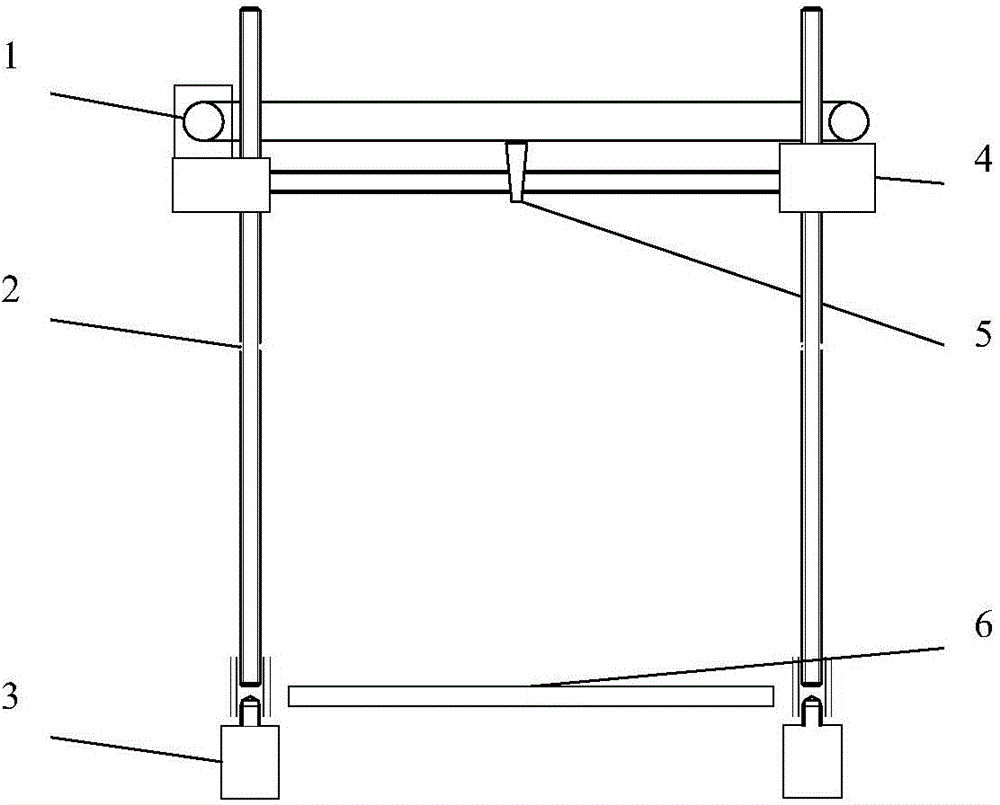
[0005] In the process of realizing the present invention, the inventor found that for some design shapes, there are certain problems in the existing 3D printing methods; 3D printing is still based on the up, down, left, and right movement of the electric thermal fusion head and the front and back movement of the tray to achieve 3D printing. Since such 3D printing is based on the integral method of drawing circles rather than linear ones, the existing 3D printing will not only Increase the difficulty of 3D modeling, but also make the 3D printing cycle longer

Method used


Image

  • 3D printer
  • 3D printer

Examples


Embodiment Construction

[0013] Before discussing the example embodiments in greater detail, it should be mentioned that specific structural and functional details disclosed herein are merely representative and for purposes of describing example embodiments of the invention. This invention may, however, be embodied in many alternative forms and should not be construed as limited to only the embodiments set forth herein.

[0014] It will be understood that although the terms "first", "second", etc. may be used herein to describe various elements, these elements should not be limited by these terms. These terms are only used to distinguish one element from another. For example, a first element could be termed a second element, and, similarly, a second element could be termed a first element, without departing from the scope of example embodiments. As used herein, the term "and / or" includes any and all combinations of one or more of the associated listed items.

[0015] It will be understood that when ...


PUM


Abstract

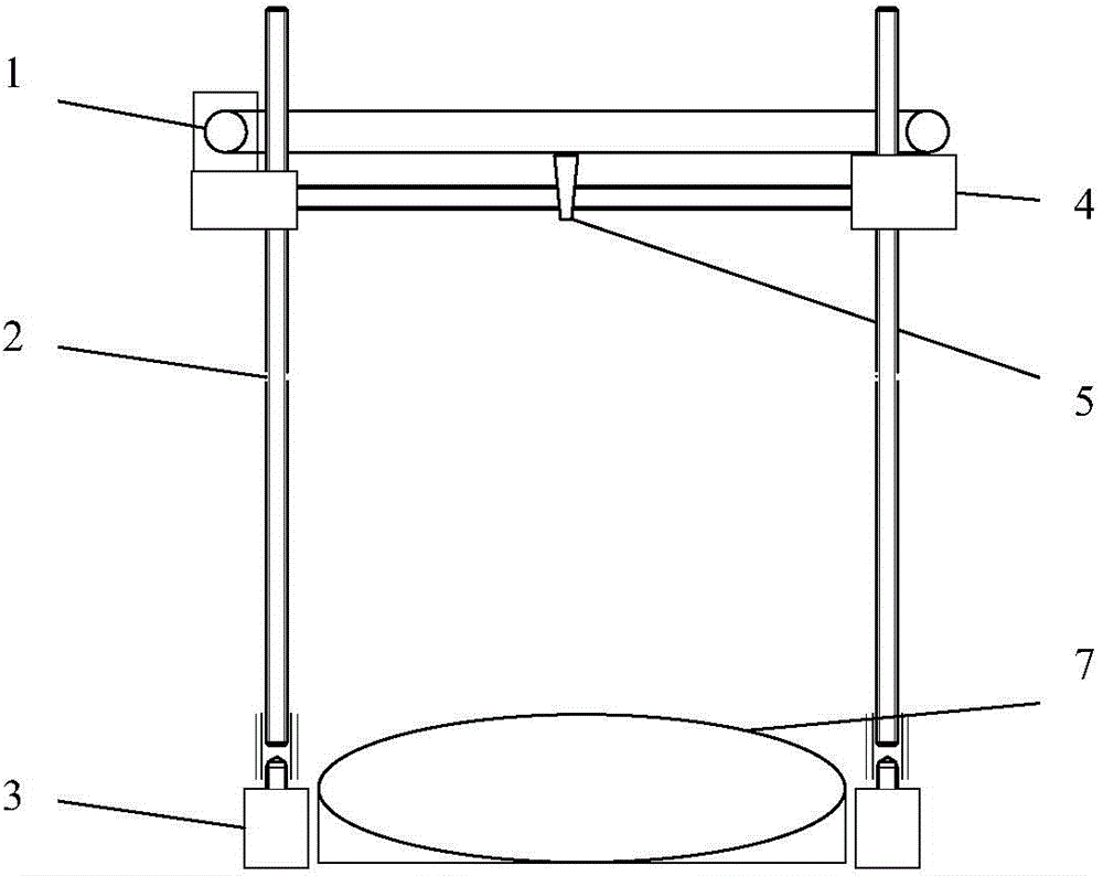
The invention provides a 3D printer which comprises a circular tray, a tray base, a first driving device and a driving device, wherein the tray base is arranged on a 3D printer frame and used for supporting the circular tray; the first driving device is arranged on the tray base, connected with the circular tray and used for driving the circular tray to rotate by taking the center of a circle of the tray as a rotating center; and the second driving device is arranged on the 3D printer frame, connected with the tray base and used for driving the tray base to do rectilinear motion in the horizontal direction so as to enable the tray base to drive the circular tray to do rectilinear motion in the horizontal direction. According to the scheme provided by the invention, the motion mode of the tray is more flexible and diverse; the circular tray which is flexible and diverse in motion mode enables the 3D printer to draw a circle on the basis of a linear mode, so that the problems of high 3D model building difficulty and long printing cycle caused by circle drawing based on an integral mode are solved; and finally, the printing property of the 3D printer is improved by adopting the technical scheme provided by the invention.

Description

technical field [0001] The invention relates to the technical field of 3D printing, in particular to a 3D printer. Background technique [0002] A 3D printer is a device that superimposes printing materials such as metal, ceramics, resin, plastic or sand layer by layer, and finally turns the design blueprint in an intelligent electronic device (such as a computer or server, etc.) into a physical device. In layman's terms, a 3D printer is a device that can print out real 3D objects. The 3D objects printed by 3D printers can be specifically molds, toys and machine parts, etc. Some 3D printers can even print food. [0003] The 3D printer based on fused deposition is a kind of 3D printer that is widely used at present. Some structures of the existing 3D printer based on fused deposition are as follows: figure 1 shown. [0004] figure 1 The partial structure of the 3D printer shown mainly includes: a conveyor belt 1, a screw rod 2, a stepping motor 3, a support 4, an electric...

Claims


Application Information

Patent Timeline
IPC IPC(8): B29C67/00B22F3/115B28B1/00B33Y30/00
Inventor 李雅杰黄甜甜汤巍敏张尤长武毅赵阳刘子曜李玲郑鑫王金莹
Owner BAIDU ONLINE NETWORK TECH (BEIJIBG) CO LTD
Learn More