Door lock and household appliances using door lock

A technology for home appliances and door locks, applied in the field of door locks

Active Publication Date: 2015-09-09
ILLINOIS TOOL WORKS INC
View PDF5 Cites 9 Cited by
  • Summary
  • Abstract
  • Description
  • Claims
  • Application Information

AI Technical Summary

Problems solved by technology

This situation may require a service call to unlock the door and open the door

Method used


Image

  • Door lock and household appliances using door lock
  • Door lock and household appliances using door lock
  • Door lock and household appliances using door lock

Examples


Embodiment Construction

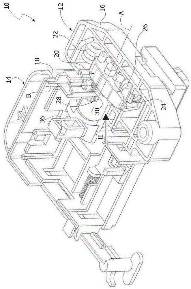
[0028] refer to figure 1 , numeral 10 denotes a door lock for home appliances according to the present invention. The door lock 10 includes a locking unit 12 and an electrical control unit 14 . The locking unit 12 and the electrical control unit 14 may be two separate units provided with respective housings 16 , 18 separate from each other. Alternatively, the locking unit 12 and the electrical control unit 14 may be integrated into a single housing.

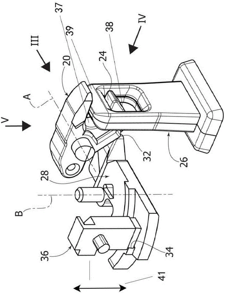
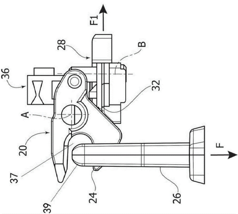
[0029] The locking unit 12 comprises a cam 20 rotatable about a first axis of rotation A relative to the housing 16 . Cam 20 is rotatable about axis A between a locked position and a released position.

[0030] The cam 20 is associated with a first spring 22 . The spring 22 has a bistable function. When the door of the appliance is in the open position, the spring 22 pushes the cam 20 to the release position. When the door of the appliance is closed, the spring 22 pushes the cam 20 into the locked position.

[0031] The ca...


PUM


Abstract

The invention relates to a door lock and household appliance using the door lock. The door lock includes a shell having an opening where a hook is inserted, the hook being loaded by a door of the device; a cam which can rotate relative to the shell around a first axis A between a lock position and a release position, wherein in the lock position, the cam suits to lock the hook in a closed gate; a slider member cooperated with the cam and moving between the release position and the lock position, wherein in the release position, the cam free rotates around the first axis A, and in the lock position, the slider member locks the cam in the lock position; and a lock pin for locking the slider member in the lock position, wherein the slider member can rotate around a second axis B between the release position and the lock position. The technical scheme of the invention can more effectively apply a driving force from an electromagnetic driver to the lock pin so as to avoid the deadlock phenomenon and improve the feasibility for manufacturing the door lock.

Description

technical field [0001] The present invention relates to a door lock for household appliances such as washing machines, dryers, washer-dryers and the like. Background technique [0002] WO2013181289 describes a door lock for equipment comprising: [0003] - a housing having an opening for the insertion of a hook carried by the door of the device; [0004] - a cam which is rotatable about an axis of rotation relative to the housing between a locking position and a release position wherein in the locking position the cam is adapted to lock the hook in the closed door position; [0005] - a slider cooperating with the cam and movable between a release position, in which the cam is free to rotate about said axis of rotation, and a locking position, wherein in the locking position, the slider locks the cam in the locked position; and [0006] - An electromagnetic actuator comprising a locking pin adapted to lock said slider in a locked position. [0007] When the load of cloth...

Claims


Application Information

Patent Timeline
Patent Type & Authority Applications(China)
IPC IPC(8): D06F37/42E05B47/06E05B15/00D06F58/20
Inventor 博杨·彼斯克
Owner ILLINOIS TOOL WORKS INC
Why Eureka
Try Eureka