Chuck

A chuck and disk body technology, applied in the directions of large fixed members, clamping, and support, can solve the problems of inability to automate and lose accuracy, and achieve the effect of small simplicity, avoidance of bending, and avoidance of loss of accuracy

Inactive Publication Date: 2018-08-28
ROHM CO LTD
View PDF5 Cites 0 Cited by
  • Summary
  • Abstract
  • Description
  • Claims
  • Application Information

AI Technical Summary

Problems solved by technology

Loading with grippers is therefore ruled out and cannot be automated
In addition, what is considered a special defect is the loss of accuracy in processing

Method used


Image

  • Chuck
  • Chuck
  • Chuck

Examples


Embodiment Construction

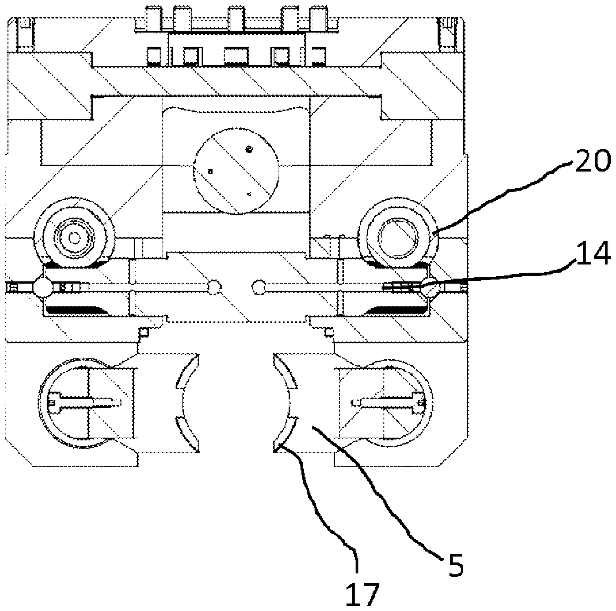
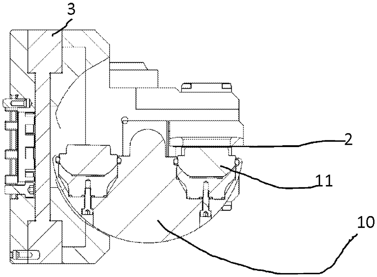
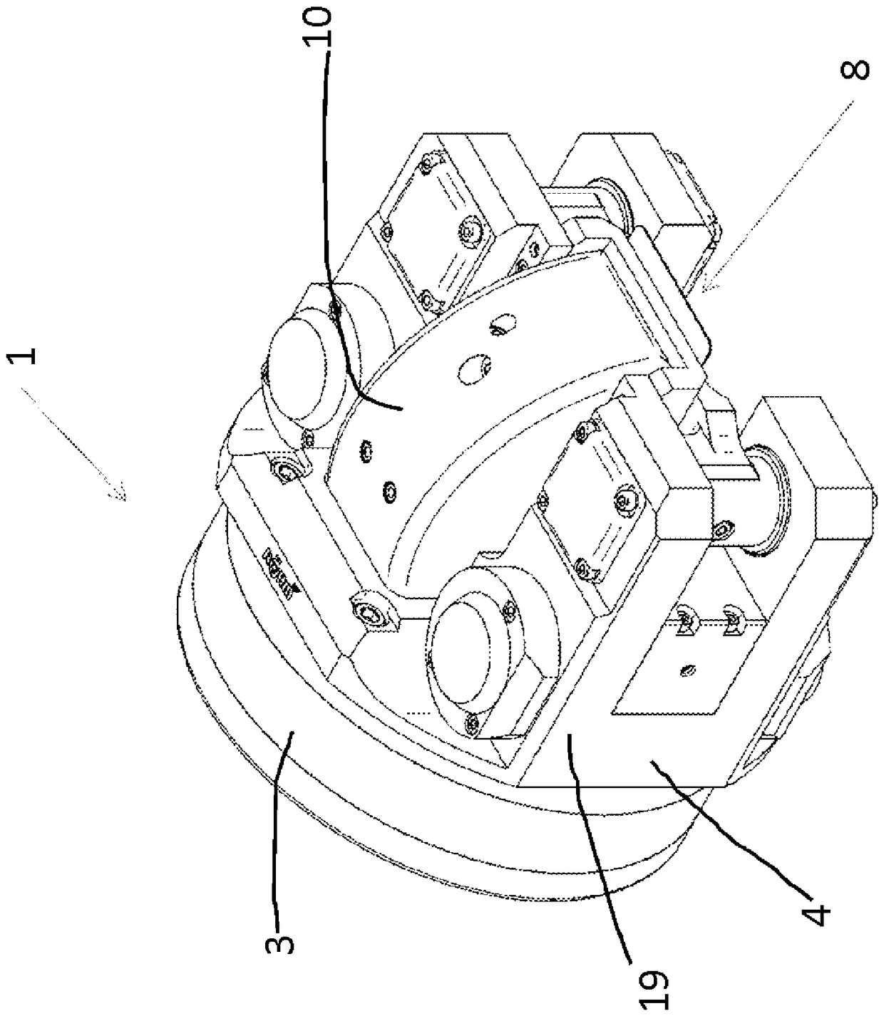
[0024] In the attached picture, figure 1 A chuck 1 is shown, which is used for clamping thin-walled workpieces 2 , ie, in the exemplary embodiment shown in the drawing, for clamping thin-walled printed circuit boards. The chuck 1 has a disc body 3 on which two U-shaped brackets 4 are arranged, and clamping blocks 5 are arranged between the free ends of these brackets, and the clamping blocks are used for clamping the workpiece 2 . A workpiece carrier 6 is assigned to the disk body 3 , that is, in the exemplary embodiment shown in the drawing, between the free ends of the U-shaped brackets 4 . The clamping block 5 is designed as a clamping pin which can be adjusted perpendicular to the plane of the workpiece carrier 6 .

[0025] The disk 3 can be adjusted between a first rotational position for machining the upper side 7 of the workpiece 2 and a second rotational position for machining the lower side 8 of the workpiece. In order that the workpiece 2 can be reached by the tool...


PUM


Abstract

The present invention relates to a spannfutter, for clamping thin-wall type workpieces, including a body, which may be adjusted between the first rotation position at the upper side of a processing workpiece and the second rotation position at the lower side of a processing workpiece; a workpiece bracket arranged to the body, which has a hole as an inlet getting to the lower side of the workpiece; and at least two clamp splices which are supported on the body and adjusted with respect to the workpiece bracket. A workpiece structural support is provided, being adjusted between a first position for supporting the lower side of the workpiece in the first rotation position and a second position for supporting the upper side of the workpiece in the second rotation position, having at least one pinion for realizing rotational coupling through a provided adjustable piston with dentitions, arranged in a cylindrical cavity and adjusted via pressure medium in the body.

Description

technical field [0001] The invention relates to a chuck for clamping thin-walled workpieces, which has a disc body, a workpiece bracket assigned to the disc body, and at least two chucks that are supported on the disc body and can be adjusted relative to the workpiece bracket. clamp block. Background technique [0002] Such chucks are known from practice and are provided by the applicant under the designation KPF-MT as force-actuated flat chucks for clamping and subsequent processing of thin-walled workpieces, ie printed circuit boards. Normally, printed circuit boards are processed from both sides, for which the workpiece is turned. For this purpose, counterbore holes are inserted in the printed circuit board, into which pins are introduced, with a slight interference in order to ensure sufficient precision. Loading with grippers is therefore ruled out and cannot be automated. In addition, what is considered a special defect is the loss of accuracy in processing. Conte...

Claims


Application Information

Patent Timeline
Patent Type & Authority Patents(China)
IPC IPC(8): B23Q1/52B23Q3/02
CPCB23Q3/065B23Q1/525B25B5/006B25B5/061B25B5/145B25B5/163
Inventor T.拜尔
Owner ROHM CO LTD
Why Eureka
Try Eureka