Multi-stage agglomeration and rotational flow combined method for removing liquid from gas

A technology of gas and swirling, applied in separation methods, chemical instruments and methods, and separation of dispersed particles, etc., can solve problems such as weakening of swirling effects, and achieve the effects of easy processing, simple structure, and improved liquid removal efficiency

Inactive Publication Date: 2015-09-30
QINGDAO JINGRUN PETROCHEM ENG
View PDF4 Cites 9 Cited by
  • Summary
  • Abstract
  • Description
  • Claims
  • Application Information

AI Technical Summary

Problems solved by technology

The purpose of separation can only be achieved when the separation time of the droplets is less than the residence time of the gas in the swirl field. Increasing the length of the cylinder can increase the residence time of the fluid in the swirl field and improve the efficiency of liquid removal, but as the axial distance increases As the velocity increases, the hoop velocity gradually decreases, the separation power of the droplet becomes smaller and smaller, and the swirl effect is weakened; secondly, because the liquid is still in contact with the gas, the flowing gas will break up the liquid gathered in the wall area at any time, making the liquid In addition, due to the fluidity of the liquid, after the liquid coalesces into a larger volume along the wall, the gravity will naturally break the surface tension, forming small particles and returning to the gas. Therefore, even if the swirling flow scheme is used in the existing technology, since the liquid cannot be drawn out at any time, the separated liquid will be broken again under the action of the air flow, and become small droplets, which are re-involved in the smoke

Method used


Image

  • Multi-stage agglomeration and rotational flow combined method for removing liquid from gas
  • Multi-stage agglomeration and rotational flow combined method for removing liquid from gas
  • Multi-stage agglomeration and rotational flow combined method for removing liquid from gas

Examples


Embodiment

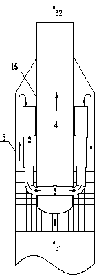
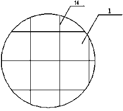
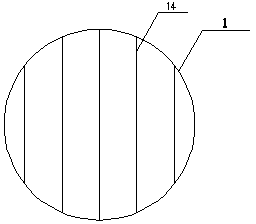
[0051] It is used for dehydration of flue gas in wet flue gas desulfurization unit. The flue gas volume is 200,000 standard cubic meters per hour, the water content in the flue gas is 97099kg / h, the diameter of the tower body is 6000mm, the coalescing area is in the form of a grid, 150mm below the multi-stage cyclone eliminator, the channel size is 30mm, and the height is 1000mm. It is a hydrophilic plastic, and six sets of multi-stage cyclone separators of the same size are set between the exhaust tube and the tower body. Each set of separators has three stages, the shell diameter D1=800mm, the height L1=1440mm, D2= 680mm , L2=1224mm, D3=560mm, L3=1008mm, d=2750mm, H=420mm, α=0°, S=60mm, there are 4 swirl blades in each stage, the total pressure drop of the dehydrator is 1085Pa, and the exhaust gas contains The amount of water is almost zero.


PUM


Abstract

The invention provides a multi-stage agglomeration and rotational flow combined method for removing liquid from gas and belongs to the technical field of gas-liquid separation. The method is particularly used for dehydrating for removing liquid from gas discharged from a wet-process flue gas desulphurization device. According to the method, adopted devices comprise a tower body, an agglomeration zone, a multi-stage rotational flow liquid-removal zone and an exhaust barrel, wherein the agglomeration zone is composed of multi-stage staggered agglomeration plates; the multi-stage rotational flow liquid removal zone comprises a multi-stage cyclone and a connecting barrel; gas from a lower position is discharged from the exhaust barrel after being subjected to liquid removal through the agglomeration zone and the multi-stage rotational flow liquid removal zone and separated liquid is drained through a liquid drainage pipe and then flows into other lower zones.

Description

technical field [0001] The invention belongs to the technical field of gas-liquid separation, and in particular relates to a multi-stage coalescing cyclone gas liquid removal method. Background technique [0002] Flue gas desulfurization mostly adopts a wet process. The so-called wet process uses an absorbent prepared as a slurry to wash the flue gas and remove the SO in the flue gas. 2 It is absorbed into the slurry and reacts with the absorbent. The core device is the absorption tower. Since most of the reaction of the absorption tower adopts spray washing, the treated flue gas contains a large number of mist droplets. If the mist is allowed to When the droplets are taken out of the absorption tower, the mist droplets will be discharged from the chimney with the flue gas, and fall around the chimney to form "light rain", thereby polluting the environment. From the point of view of energy saving, a large amount of slurry is taken out, which is also a loss to the operation...

Claims


Application Information

Patent Timeline
Patent Type & Authority Applications(China)
IPC IPC(8): B01D45/02B01D45/14B01D51/02
Inventor 石宝珍房媛媛李亮
Owner QINGDAO JINGRUN PETROCHEM ENG
Why Eureka
Try Eureka