Liquid baffle structure and evaporator of air conditioning equipment

A technology for air-conditioning equipment and liquid baffles, which is applied to evaporators/condensers, lighting and heating equipment, refrigeration and liquefaction, etc., can solve problems such as low liquid removal efficiency, achieve low liquid removal efficiency, and improve liquid removal. The effect of efficiency

Active Publication Date: 2017-02-22
GREE ELECTRIC APPLIANCES INC
View PDF6 Cites 0 Cited by
  • Summary
  • Abstract
  • Description
  • Claims
  • Application Information

AI Technical Summary

Problems solved by technology

[0009] One of the objectives of the present invention is to propose a liquid baffle structure and an evaporator of an air-conditioning device with the liquid baffle, which solves the technical problem of low liquid removal efficiency in the prior art

Method used


Image

  • Liquid baffle structure and evaporator of air conditioning equipment
  • Liquid baffle structure and evaporator of air conditioning equipment
  • Liquid baffle structure and evaporator of air conditioning equipment

Examples


Embodiment 1

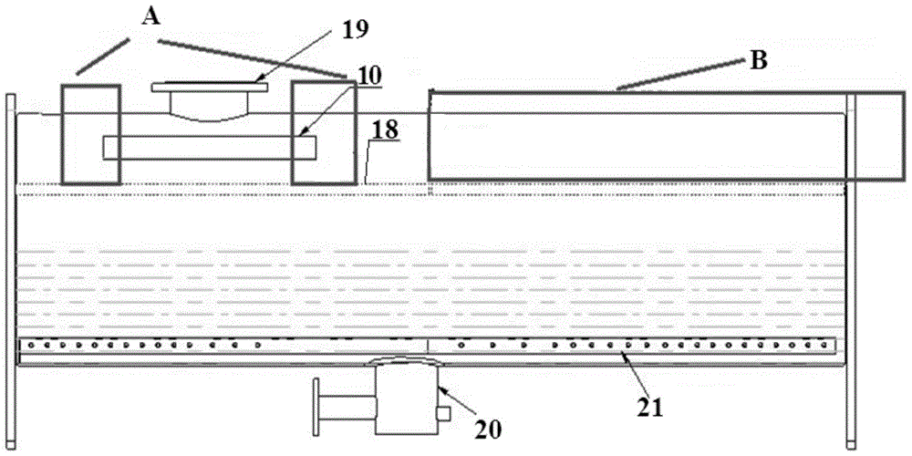
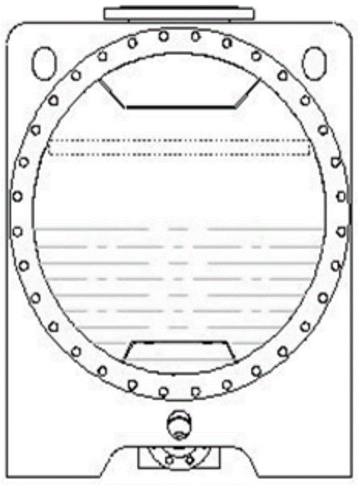
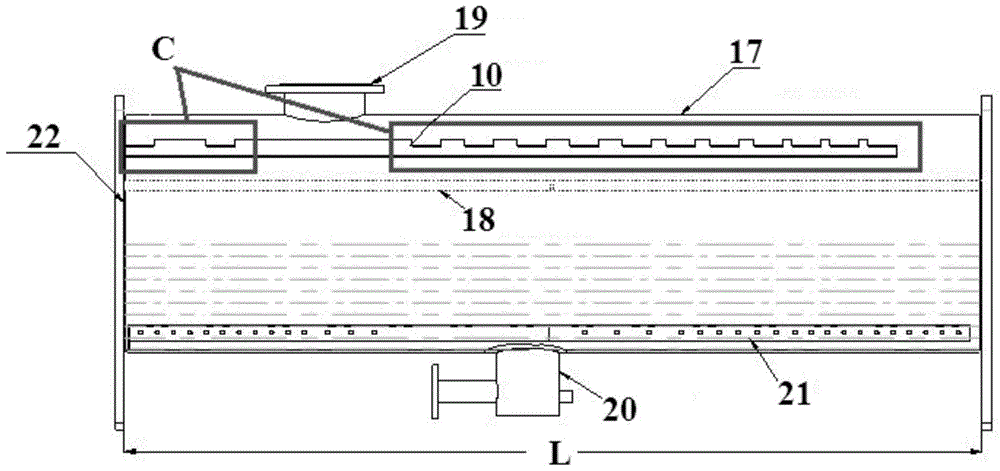
[0062] Such as Figure 9 ~ Figure 23 As shown, the liquid baffle structure provided by the embodiment of the present invention is used to block the liquid droplets in the refrigerant gas of the air conditioner. The liquid baffle structure includes a droplet blocking area and a droplet falling part (or called: drop point) 11 of the liquid baffle body portion 1, the drop blocking area is configured to enable the droplets condensed thereon to collect into the drop drop portion 11, the drop drop portion 11 is lower than the area around the drop drop portion 11 .

[0063] Since the droplet falling part 11 of the liquid baffle body provided by the embodiment of the present invention is lower than the area around the droplet falling part 11, compared with the trapezoidal structure in the prior art, there is a trapezoidal structure below the trapezoidal structure. On the droplet falling surface, the droplet falling part 11 on the droplet falling surface is at the same height as the s...

Embodiment 2

[0088] Such as Figure 24 and Figure 25 As shown, the difference between this embodiment and Embodiment 1 is that the cross-section of the body part 1 of the liquid baffle in the embodiment of the present invention includes a broken-line part. At this time, the outer contour of the section perpendicular to the longitudinal direction of the liquid baffle body 1 is in the shape of a broken line.

[0089] Such as Figure 24 The shown liquid baffle structure has a droplet falling part 11, such as Figure 25 There are two droplet falls 11 in the shown liquid baffle structure. Of course, more droplet falling parts 11 can also be provided as required.

Embodiment 3

[0091] Such as Figure 26 As shown, the difference between this embodiment and Embodiment 1 is that there are two droplet falling parts 11 in the liquid baffle structure in the embodiment of the present invention. Of course, more droplet falling parts 11 can also be provided as required.


PUM


Abstract

The invention discloses a liquid baffle structure and an evaporator of an air conditioner, and relates to the technical field of air conditioners. The technical problem of low liquid removal efficiency in the prior art is solved. The liquid baffle structure includes a liquid baffle structure for blocking liquid droplets in the refrigerant gas of the air conditioner, and is characterized in that the liquid baffle structure includes a liquid baffle body part having a droplet blocking area and a droplet falling part, The droplet barrier is configured such that droplets condensed thereon collect into the droplet fall, which is lower than the area around the droplet fall. The evaporator of the air conditioner includes a housing, a gas-liquid separator arranged in the housing, and a liquid baffle provided by the present invention, the body of the liquid baffle is located above the gas-liquid separator, and is fixedly connected to the inner wall of the housing . The invention is used to improve the liquid removal efficiency of the liquid baffle structure, thereby improving the performance of the compressor.

Description

technical field [0001] The invention relates to the technical field of air conditioning, in particular to a liquid baffle structure and an evaporator of an air conditioner provided with the liquid baffle. Background technique [0002] After the refrigerant gas evaporated in the evaporator of the existing centrifuge passes through the gas-liquid separator, some liquid droplets will still be entrained. If this part of the liquid droplets enter the compressor (that is, the phenomenon of "suction with liquid"), it will cause two hazards: 1. Liquid hammer phenomenon, damage to the blade; 2. The performance of the compressor will deteriorate, and these hazards will be slow And continuous. [0003] Such as Figure 1 to Figure 8 As shown, in the prior art, in order to reduce the amount of liquid carried by suction, a liquid baffle device is usually added to the upper part of the gas-liquid separator 18 inside the evaporator. The liquid baffle device is referred to as the liquid baf...

Claims


Application Information

Patent Timeline
Patent Type & Authority Patents(China)
IPC IPC(8): F25B41/00F25B39/02F25B41/40
CPCF25B39/02F25B43/00F25B2339/02
Inventor 杨旭峰杨锦源赵艳陈红胡东兵万仁杰熊炼
Owner GREE ELECTRIC APPLIANCES INC
Why Eureka
Try Eureka