

Liquid impact preventing liquid storage tank
A liquid storage tank and liquid-proof technology, which is used in refrigeration and liquefaction, refrigeration components, refrigerators, etc., can solve the problems of low liquid removal efficiency, and achieve the effect of improving liquid removal efficiency and avoiding liquid shock.
- Summary
- Abstract
- Description
- Claims
- Application Information
AI Technical Summary
Problems solved by technology
Method used
Image

Examples
Embodiment 1
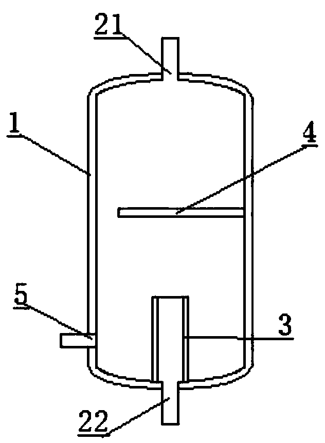
[0020] This embodiment provides an anti-liquid shock storage tank, such as figure 1 Comprising a columnar tank body 1, the bottom of the tank body 1 is provided with an air inlet 22, and the top of the tank body is provided with an exhaust port 21, and also includes an overflow plate 3 and a baffle plate 4 located in the tank body; The baffle 4 is cylindrical and surrounds the air inlet; the baffle is arranged along the radial direction of the cylindrical tank, and is shielded above the air inlet; the side of the tank is also provided with a liquid discharge port 5 .
[0021] In this embodiment, the cylindrical tank body is integrally formed with alloy materials. The overflow plate is made of stainless steel, and its bottom is fixed in the tank by welding. The baffle is a stainless steel plate body, and its edge is welded on the inner wall of the tank body.
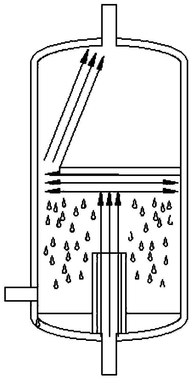
[0022] Such as figure 2 , the refrigerant gas entering the tank collides with the baffle and turns, and the liquid ...
Embodiment 2
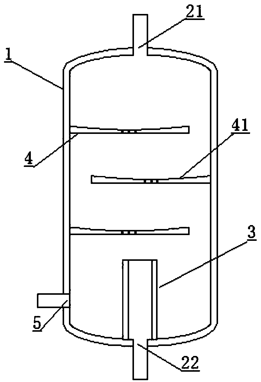
[0024] This embodiment provides an anti-liquid shock storage tank, such as Figure 3-5 , comprising a columnar tank body 1, the bottom of the tank body 1 is provided with an air inlet 22, the top of the tank body is provided with an exhaust port 21, and also includes an overflow plate 3 and three baffle plates 4 located in the tank body; The overflow plate is cylindrical and surrounds the air inlet; the baffle plate is arranged along the radial direction of the cylindrical tank body, and is shielded above the air inlet; the side of the tank body is also provided with a liquid discharge port.
[0025] Further, two adjacent liquid baffles are arranged alternately.
[0026] Furthermore, the surface of the liquid baffle has annular concave grooves 42 . The annular dimples are formed on the surface of the spoiler by stamping.
[0027] Preferably, the top of the liquid baffle has a concave surface 41 , and the bottom of the concave surface is provided with a liquid leakage through...
PUM
 Abstract
Description
Claims
Application Information