Automatic focusing device and method

A technology for auto-focusing and beam detection, applied in the field of optical detection, which can solve problems such as slow focusing speed, achieve precise auto-focusing, and solve the effect of multiple operations

Active Publication Date: 2015-10-21
GUANGZHOU INST OF BIOMEDICINE & HEALTH CHINESE ACAD OF SCI
View PDF5 Cites 2 Cited by
  • Summary
  • Abstract
  • Description
  • Claims
  • Application Information

AI Technical Summary

Problems solved by technology

[0005] The purpose of the present invention is to provide an autofocus device and method, which can realize autofocus quickly and accurately, and solve the problems of multiple operations and slow focus speed in the process of taking pictures

Method used


Image

  • Automatic focusing device and method
  • Automatic focusing device and method
  • Automatic focusing device and method

Examples


Embodiment 1

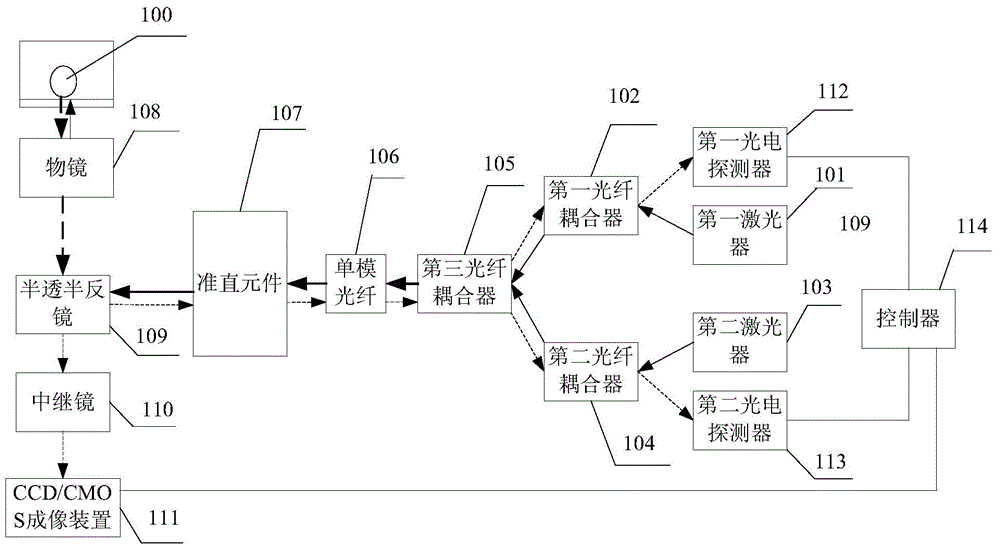
[0073] figure 1 It is a structural block diagram of an autofocus device provided in Embodiment 1 of the present invention; figure 1 As shown, the device includes: a first laser 101, a first fiber coupler 102, a second laser 103, a second fiber coupler 104, a third fiber coupler 105, a single-mode fiber 106, a collimation element 107, an objective lens 108 , half mirror 109 , relay mirror 110 , CCD / CMOS imaging device 111 , first photodetector 112 , second photodetector 113 and controller 114 .

[0074] Wherein, the first laser 101 is used to emit a first detection beam.

[0075] The first fiber coupler 102 is configured to perform coupling processing on the first detection beam.

[0076] The second laser 103 is used to emit a second detection beam, wherein the wavelength of the second detection beam is different from that of the first detection beam.

[0077] The second fiber coupler 104 is used for coupling the second detection beam.

[0078] The third fiber coupler 105 i...

Embodiment 2

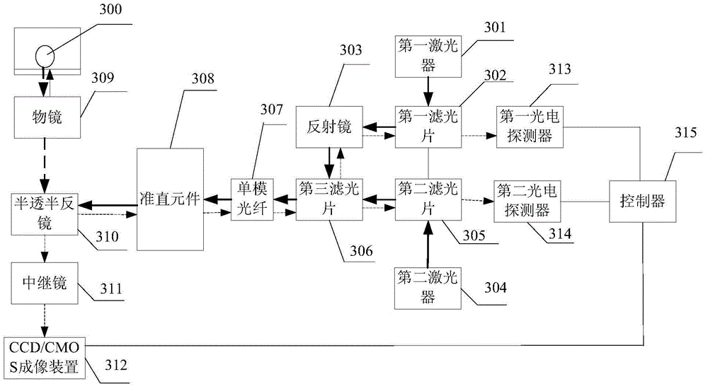
[0098] image 3 It is a structural block diagram of an autofocus device provided in Embodiment 2 of the present invention; image 3 As shown, on the basis of the above embodiments, the first optical fiber coupler, the second optical fiber coupler and the third optical fiber coupler are replaced by the first optical filter, the second optical filter and the third optical filter respectively .

[0099] On the basis of the above embodiments, the device further includes: a reflector, configured to reflect the first detection beam, so that the first detection beam enters the third optical filter.

[0100] Correspondingly, such as image 3 As shown, the above-mentioned device includes: a first laser 301, a first optical filter 302, a mirror 303, a second laser 304, a second optical filter 305, a third optical filter 306, a single-mode optical fiber 307, a collimator Element 308 , objective lens 309 , half mirror 310 , relay mirror 311 , CCD / CMOS imaging device 312 , first photode...

Embodiment 3

[0119] Figure 4 It is a flow chart of an autofocus method provided by Embodiment 3 of the present invention. The method is executed by the autofocus device in Embodiment 1 above. Before discussing the exemplary embodiments in more detail, it should be mentioned that some Exemplary embodiments are described as processes or methods depicted as flowcharts. Although the flowcharts describe various operations (or steps) as sequential processing, many of the operations may be performed in parallel, concurrently, or simultaneously. In addition, the order of operations can be rearranged. The process may be terminated when its operations are complete, but may also have additional steps not included in the figures, and in some alternative implementations, the functions / acts noted may be in a different order than noted in the figures occur. For example, various figures shown in succession may, in fact, be executed substantially concurrently or may sometimes be executed in the reverse...


PUM


Abstract

The invention discloses an automatic focusing device and a method. The automatic focusing device adjusts the position of an objective lens via a first laser, a first optical fiber coupler, a second laser, a second optical fiber coupler, a third optical fiber coupler, a single-mode optical fiber, an alignment element, the objective lens, a semi-transmitting and semi-reflecting mirror, a relay mirror, a CCD / CMOS imaging device, a first photoelectric detector, a second photoelectric detector and a controller. Automatic focusing can be realized quickly and accurately, and the problems of multiple times of operation and slow focusing speed during a picture photographing process can be solved.

Description

technical field [0001] The invention relates to the technical field of optical detection, in particular to an automatic focusing device and method. Background technique [0002] In the field of cell research, real-time observation of cells is a very important link, including observing the shape and division of cells to study cell growth and cell activity. [0003] In the laboratory, the cells used for research generally grow on the bottom surface of the culture box, and the cells are constantly moving. There is a difference in refractive index between the cells and the bottom surface of the culture box, and there is also a difference in refractive index between the outside air and the bottom surface of the culture box. Both are easy to cause reflections, so when observing cells and shooting cells, the autofocus of the shooting equipment needs to be accurate and fast. [0004] At present, there are mainly two methods for automatic focusing of shooting equipment. One is to ta...

Claims


Application Information

Patent Timeline
IPC IPC(8): G03B13/36G02B7/28
Inventor 裴端卿张骁骆健忠秦季生董建华卢俊宋研刘念张凤香麦仕文
Owner GUANGZHOU INST OF BIOMEDICINE & HEALTH CHINESE ACAD OF SCI
Why Eureka
Try Eureka