Reloading method of molding plastic extruding machine hopper

A technology for extruders and hoppers, which is applied in the field of refueling the hoppers of molding extruders. It can solve the problems of material residues, high labor intensity of workers, and difficulty in changing materials, and achieve the effect of avoiding material scattering and less additional operations.

Inactive Publication Date: 2015-11-18
CHENGDU HENGTONG ZHAOYE PRECISION MACHINERY
View PDF3 Cites 1 Cited by
  • Summary
  • Abstract
  • Description
  • Claims
  • Application Information

AI Technical Summary

Problems solved by technology

The chute is in the shape of a cuboid as a whole, with an opening on the surface and a cavity inside. The inner width of the chute is greater than the width of the opening. The cross section of the chute is in the shape of a "concave". , wherein, the lower slider is located inside the chute; the upper slider is located above the lower slider and outside the chute, the upper slider and the lower slider are connected by pipes, and the feed port of the extruder is arranged on the chute , the feeding port is located at the bottom of the chute, the upper slider and the lower slider are passed through by the pipe, and the pipe connects the feeding port and the hopper, so that when it is necessary to change the material type in the hopper, the hopper will be removed from the feeding port The position of the hopper moves outward along the chute so that the through hole of the lower slider can be connected with the discharge hole, and the hopper body can be cleaned well, the material can be discharged from the discharge hole, and the required material can be filled. The hopper body is removed, which avoids high-intensity labor and does not need to turn over the hopper body. Compared with the traditional structural form in which the hopper is fixed on the extruder, it solves the difficulty of changing material types, material residues, and labor intensity of workers. problem, to achieve the purpose of quick replacement

Method used


Image

  • Reloading method of molding plastic extruding machine hopper

Examples


Embodiment

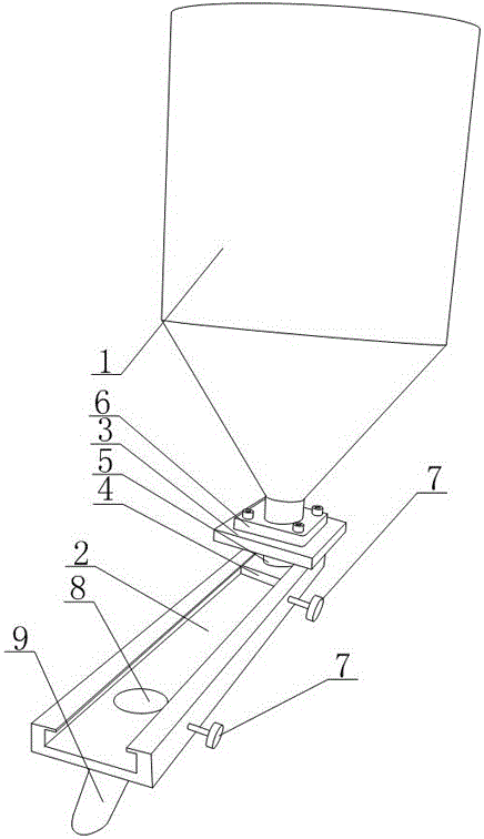
[0020] like figure 1 As shown in the figure, the present invention is a method for refilling a hopper of a molding extruder, comprising a hopper body 1, and the hopper body 1 includes a cylindrical storage cylinder, and a funnel-shaped discharging structure is connected to the bottom of the storage cylinder; it also includes The chute 2, which is fixedly installed on the extruder, is in the shape of a cuboid as a whole, with an opening on the surface and a cavity inside. The bottom of the chute 2 is provided with a feed port that communicates with the extruder, a lower slider 4 is installed in the chute 2, and two locking bolts 7 are arranged on the side of the chute 2, and the two locking bolts 7 are respectively connected to the feeder. The port corresponds to the discharge hole 8. The upper slider 3 is installed above the lower slider 4. The upper slider 3 is located on the chute 2. The upper slider 3 and the lower slider 4 are communicated through the pipe 5, and the chute...


PUM


Abstract

The invention discloses a reloading method of a molding plastic extruding machine hopper. The molding plastic extruding machine hopper comprises a hopper body, and further comprises a chute fixedly mounted on a plastic extruding machine, wherein the internal width of the chute is greater than the opening width thereof; a feed port communicated with the plastic extruding machine is formed in the bottom of the chute; an upper slide block and a lower slide block are mounted below the hopper body, are respectively positioned inside and outside the chute, and are connected through a pipe; an internal cavity of the hopper body is communicated with the feed port by a pipe; and the chute outwards extends, and is provided with an unloading hole in the bottom. The hopper body has no need to be taken down, so that higher labor intensity is prevented; and as the hopper body has no need to be overturned, compared with a structure form of a traditional hopper fixed on the plastic extruding machine, the problems of troublesome material variety replacement, material residue and high labor intensity of workers are solved, and the purpose of quick replacement is realized.

Description

technical field [0001] The invention relates to a hopper of an extruder in the sensor manufacturing industry, in particular to a material changing method for forming a hopper of an extruder. Background technique [0002] Automobile wheel speed sensor is mainly composed of sensor head, wiring harness and accessories. The function of the induction head is to cooperate with the target gear installed on the chassis of the car to measure the speed of the car wheel, which is composed of coils, magnetic poles and other parts. On this basis, in order to ensure the normal operation of the sensor, the sensor must be properly installed on the chassis of the vehicle, and there are many installation methods. There is a wheel speed sensor commonly used now, which relies on the outer steel casing of the induction head to cooperate with a part, namely, an elastic bushing, and install it into the corresponding mounting hole of the chassis. When designing the sensor, it is necessary to comb...

Claims


Application Information

Patent Timeline
IPC IPC(8): B29C47/10B29C47/08
CPCB29C48/25B29C48/285
Inventor 吴光武
Owner CHENGDU HENGTONG ZHAOYE PRECISION MACHINERY
Why Eureka
Try Eureka