Component Recognition System for Component Mounter

A component identification and mounting machine technology, applied to electrical components, electrical components, etc., can solve problems such as the inability to obtain height data and the inability to check the lead bending of components

Active Publication Date: 2018-09-28
FUJI KK
View PDF4 Cites 0 Cited by
  • Summary
  • Abstract
  • Description
  • Claims
  • Application Information

AI Technical Summary

Problems solved by technology

However, since height data cannot be obtained from a two-dimensional image of a component captured by a camera, defects in the height direction (Z direction), such as bending of the lead of the component or defects in solder bumps, cannot be inspected.

Method used


Image

  • Component Recognition System for Component Mounter
  • Component Recognition System for Component Mounter
  • Component Recognition System for Component Mounter

Examples


Embodiment Construction

[0021] Hereinafter, an example which actualized the form for carrying out this invention is demonstrated.

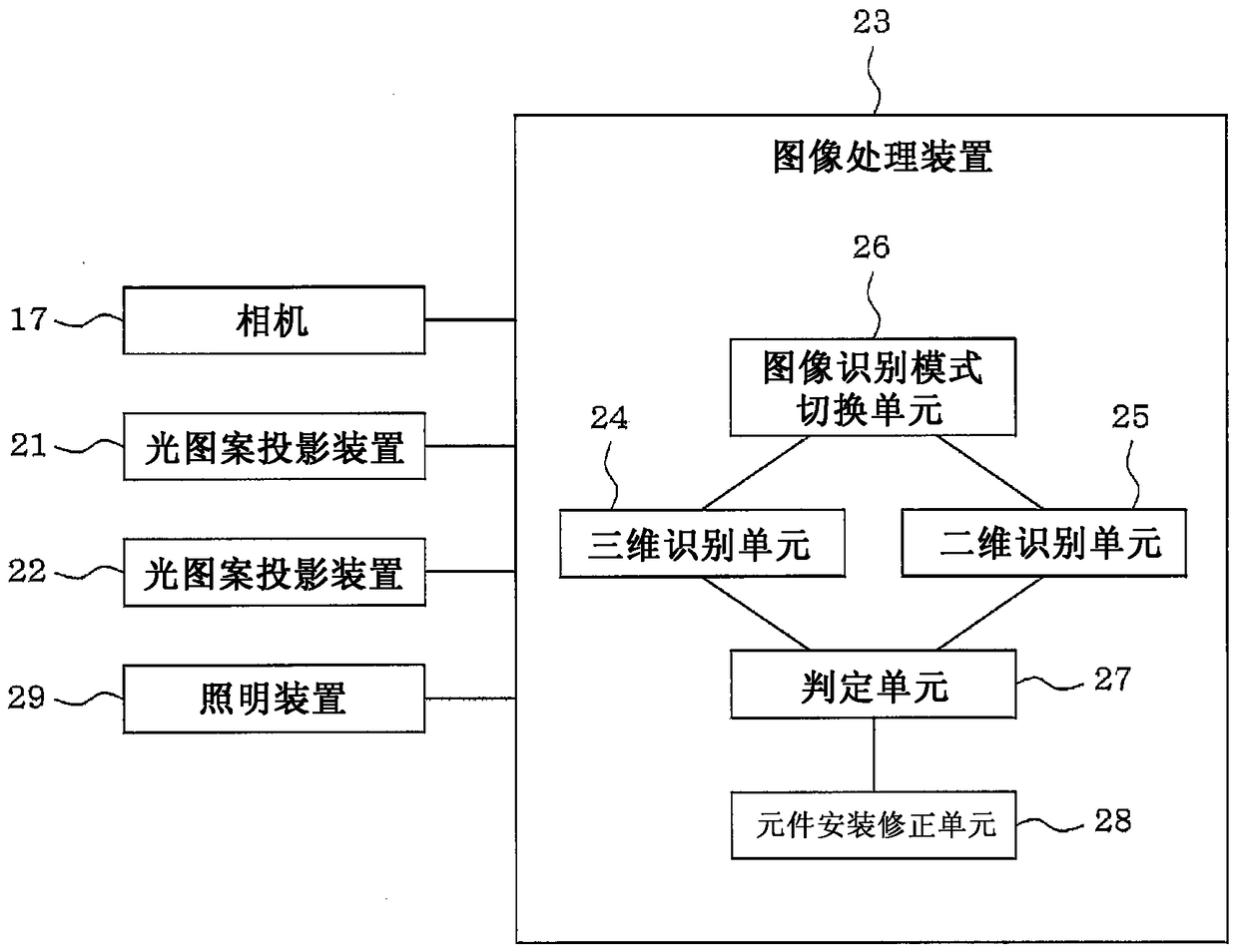
[0022] First, use Figure 1 to Figure 3 The configuration of the component recognition system of the component mounting machine of this embodiment will be described.

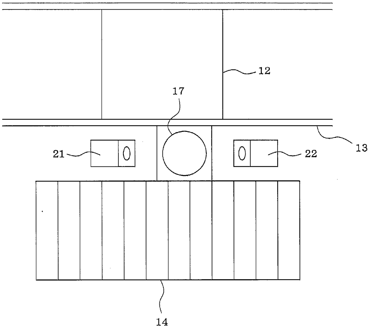
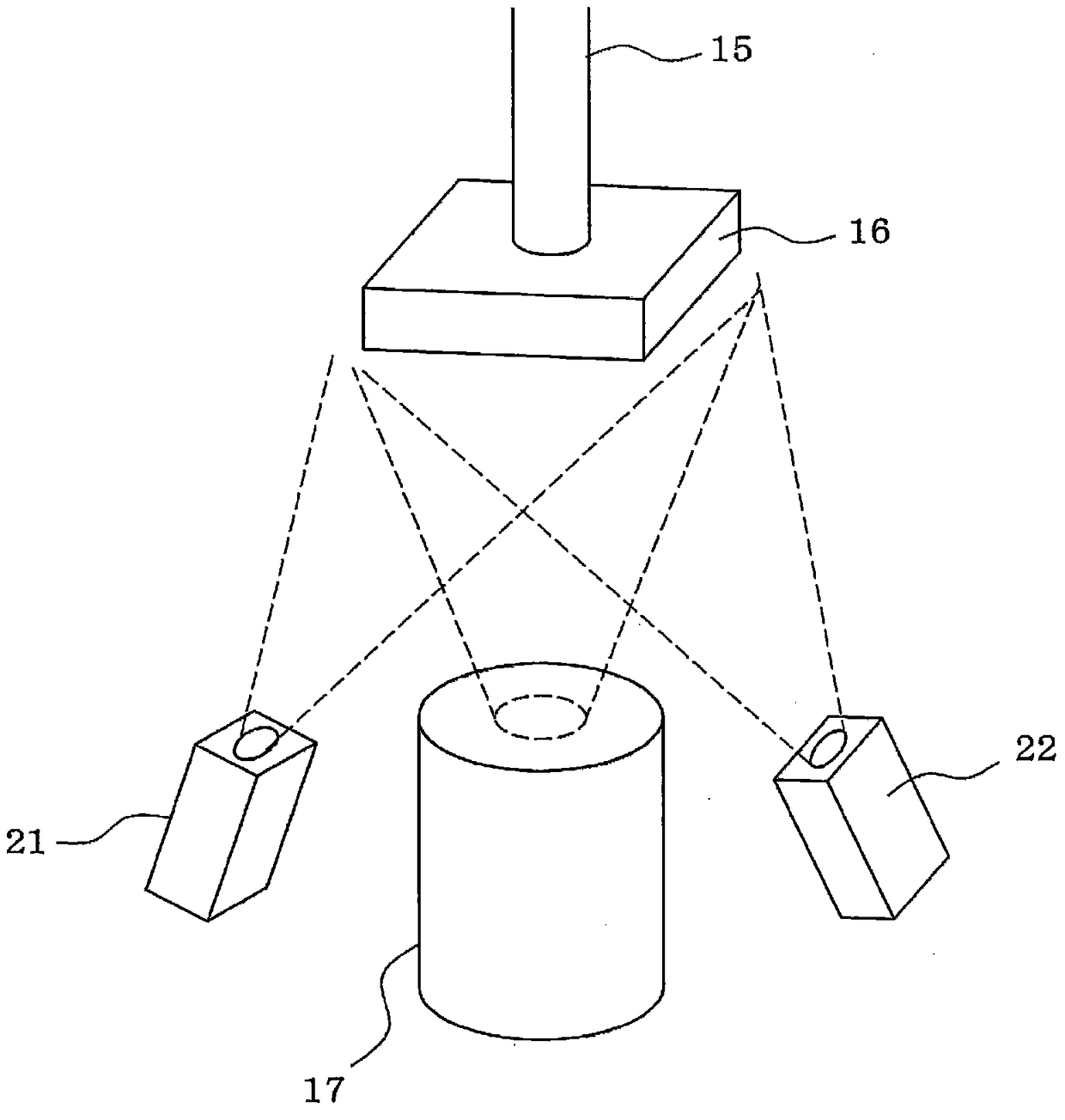
[0023] Such as figure 1 As shown, the component mounting machine is provided with: a conveyor 13 for conveying the circuit board 12, a supply component 16 (refer to figure 2 ), a component supply device 14 such as a tape feeder, and a suction nozzle 15 that holds a component 16 supplied from the component supply device 14 (see figure 2 ) mounting head (not shown), a head moving device (not shown) that moves the mounting head in XY, and the like.

[0024] Between the component supply device 14 and the conveyor 13, such as figure 2 As shown, the camera 17 which photographs the component 16 sucked by the suction nozzle 15 from below is installed upwards. Two light pattern projection devices 21 and 22 ...


PUM


Abstract

A camera 17 by which a component 16 sucked by a suction nozzle 15 in a component mounting machine is imaged from below is installed so as to face upward. Two light pattern projecting devices 21 and 22 for projecting a predetermined light pattern onto the component 16 in a direction different from an imaging direction of the camera 17 are respectively installed in both ends of the camera 17. The light pattern projecting devices 21 and 22 project the light pattern onto the component 16, an image captured by the camera 17 is processed, and the light pattern on a surface of the component 17 is recognized so as to recognize a three-dimensional shape (height) of the component 16 when viewed from below.

Description

technical field [0001] The present invention relates to a component recognition system of a component mounting machine provided with a camera that photographs a component sucked by a suction nozzle from below. Background technique [0002] Component mounting machines in recent years are equipped with an image processing function that takes pictures of components picked up by the suction nozzle from below with a camera, processes the image, and recognizes the suction posture of the component, the deviation of the suction position, and the like. However, since height data cannot be obtained from a two-dimensional image of a component captured by a camera, defects in the height direction (Z direction), such as bending of the lead of the component or defects in solder bumps, cannot be inspected. [0003] Therefore, in the component mounting machine described in Patent Document 1 (Japanese Patent No. 3926347), a three-dimensional measuring device for one-dimensional scanning usin...

Claims


Application Information

Patent Timeline
Patent Type & Authority Patents(China)
IPC IPC(8): H05K13/04H05K13/08
CPCH05K13/0812
Inventor 小林贵纮大池博史江崎弘健
Owner FUJI KK
Why Eureka
Try Eureka