
A method and device for eliminating interference of an electronic compass

An electronic compass and interference elimination technology, which is applied in the direction of measuring devices, instruments, surveying and mapping, and navigation, etc., to achieve the effects of flexible placement, overcoming interference, and accurate pointing

Active Publication Date: 2019-04-26
ZTE CORP
View PDF6 Cites 0 Cited by
  • Summary
  • Abstract
  • Description
  • Claims
  • Application Information

AI Technical Summary

Problems solved by technology

Under the development trend of mobile phone motherboards becoming smaller and smaller and their functions more and more complex, this condition is difficult to meet

Method used


Image

  • A method and device for eliminating interference of an electronic compass
  • A method and device for eliminating interference of an electronic compass
  • A method and device for eliminating interference of an electronic compass

Examples


Embodiment Construction

[0048] The preferred embodiments of the present invention will be described in detail below in conjunction with the accompanying drawings. It should be understood that the preferred embodiments described below are only used to illustrate and explain the present invention, and are not intended to limit the present invention.

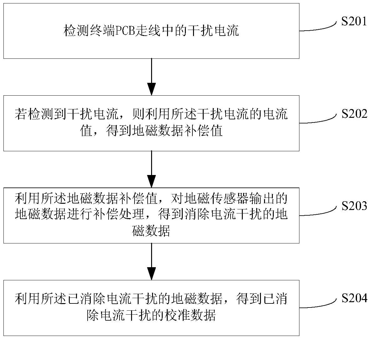
[0049] figure 2 It is a schematic block diagram of the calibration method of the electronic compass provided by the present invention, such as figure 2 shown, including:

[0050] Step S201: Detect the interference current in the terminal PCB wiring.

[0051] Specifically, firstly, the detection resistor is connected in series in the terminal PCB trace, and the voltage value at both ends of the detection resistor connected in series in the terminal PCB trace is collected, and then the voltage value at both ends of the detection resistor and the resistance value of the detection resistor are used to , to obtain the current value of the interference curr...


PUM


Abstract

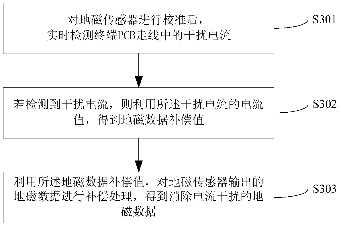
An interference elimination method for an electronic compass, comprising the following steps: 1. Checking an interference current in the PCB wiring of a terminal in real time after calibrating a geomagnetic sensor; 2. if the interference current is detected, then utilizing the current value of the interference current to obtain a geomagnetic data compensation value; 3. utilizing the geomagnetic data compensation value to compensate the geomagnetic data outputted by the geomagnetic sensor so as to obtain the geomagnetic data with the interference current eliminated. Also disclosed is an interference elimination device of the electronic compass. The interference elimination method and device of the electronic compass avoid the interference of large-current PCB wiring with the geomagnetic sensor.

Description

technical field [0001] The invention relates to electronic compass technology, in particular to a method for eliminating interference of an electronic compass and a related device. Background technique [0002] Geomagnetic sensors can realize applications such as electronic compass functions and auxiliary navigation. With the continuous development of microelectronics integration technology, processing technology and material technology, the research, manufacture and application of geomagnetic sensors have also reached an unprecedented level. At present, geomagnetic sensors can be divided into planar electronic compass and three-dimensional electronic compass according to whether there is inclination compensation or not. They can also be divided into magnetoresistive effect sensors, Hall effect sensors and fluxgate sensors according to different sensors. Magnetoresistive sensors can already be fabricated on silicon wafers and form products. Geomagnetic sensors for mobile p...

Claims


Application Information

Patent Timeline
Patent Type & Authority Patents(China)
IPC IPC(8): G01C17/38
CPCG01C17/32G01C17/38
Inventor 张绍磊童向杰刘玉鹏
Owner ZTE CORP
Learn More