
A hand brake light switch structure

A hand brake and light switch technology, applied in the direction of electric switches, motor vehicles, electrical components, etc., can solve the problems of easy damage, increase the resistance of the hand brake, and the inability to light the hand brake light, etc., to achieve simple operation and reasonable structure Effect

Active Publication Date: 2017-07-21
ZHEJIANG YANGMING AUTO PARTS
View PDF4 Cites 0 Cited by
  • Summary
  • Abstract
  • Description
  • Claims
  • Application Information

AI Technical Summary

Problems solved by technology

Then, the existing handbrake light switch depends on the driving of the handbrake for turning on and off, so that a driving structure needs to be set on the handbrake lever, which increases the resistance when the handbrake is pulled up, and the driving structure is stressed every time it is operated. It is easy to be damaged. Once the driving structure is damaged, the handbrake light cannot be turned on, which will affect normal use and parking safety.

Method used


Image

  • A hand brake light switch structure
  • A hand brake light switch structure
  • A hand brake light switch structure

Examples


Embodiment 2

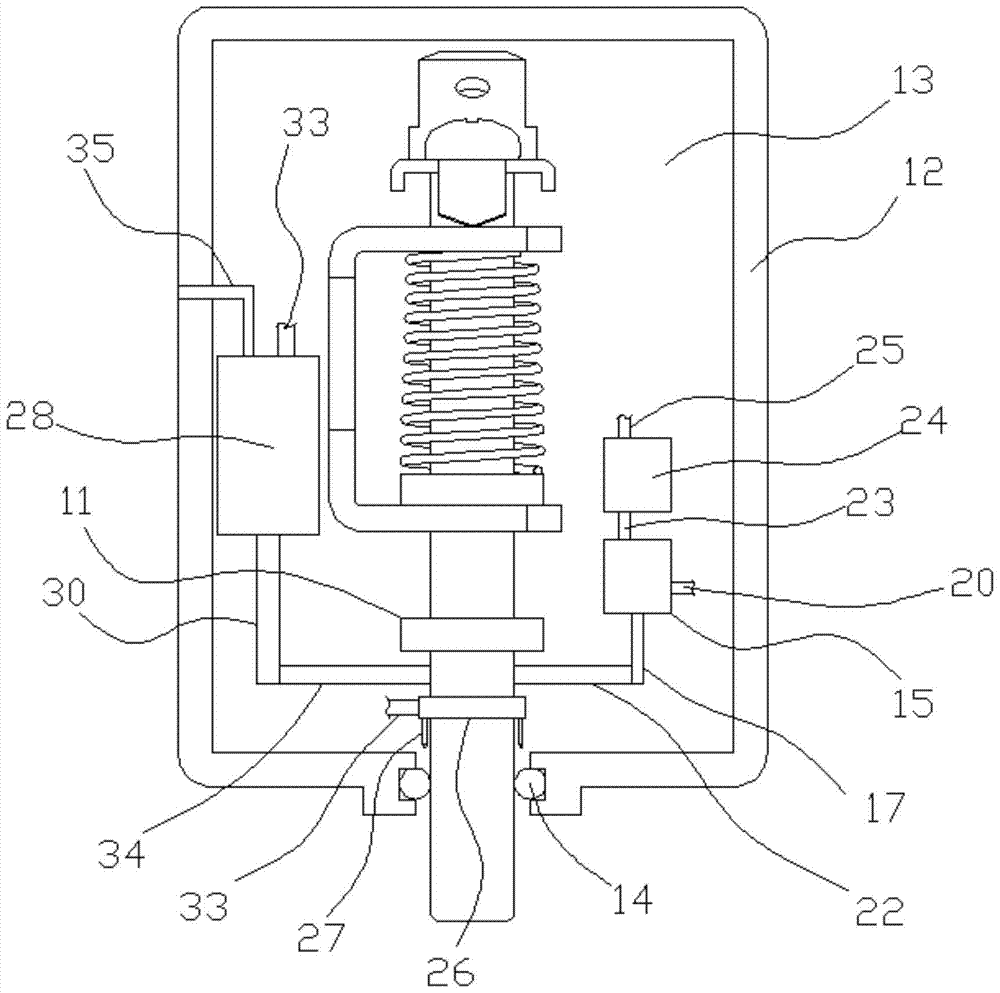
[0025] Embodiment 2: the basic structure and implementation mode of this embodiment are the same as embodiment 1, and its difference is, as Figure 3 to Figure 5 As shown in , the button column is provided with an outer limit step 11, and the outer limit step and the button step are respectively located on both sides of the lower shelf. The outer limit step can define the moving pole of the button column. When the button column is pressed and moves inward to the outer limit step and touches the lower shelf, it cannot continue to move inward, which can prevent the return spring from being over-pressed.

[0026] It also includes an insulating case 12, the space in the insulating case is a switch chamber 13, the main bracket, pins, return springs, and fixing screws are all in the switch chamber, and the insulating case is provided with an outer opening. The outer end of the button column extends out of the outer opening, and a sealing ring is arranged between the outer wall of th...


PUM


Abstract

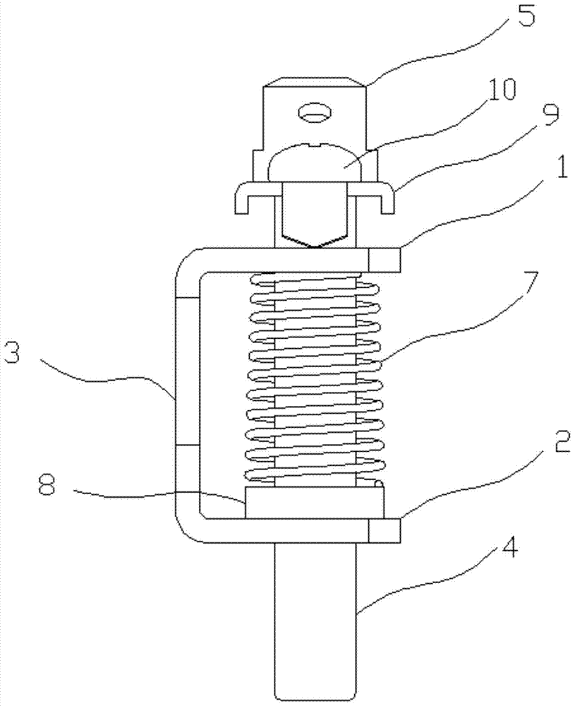
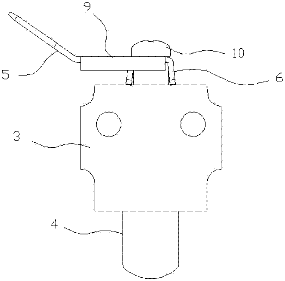
The invention discloses a hand brake lamp switch structure, and aims at providing a hand brake lamp switch structure, which is reasonable in structure, and is capable of effectively switching connection and disconnection states of a hand brake lamp circuit, so as to smoothly realize lightening and extinguishing of a hand brake lamp. The hand brake lamp switch structure is simple to operate; and lightening of the hand brake lamp is independent on drive of a hand brake lever. The hand brake lamp switch structure comprises a main bracket, wherein the main bracket comprises an upper bracket plate, a lower bracket plate and a vertical bracket plate; the vertical bracket plate is connected with the upper bracket plate and the lower bracket plate; the upper bracket plate is parallel to the lower bracket plate; two button holes are formed in the main bracket, and are respectively located on the upper bracket plate and the lower bracket plate; one button column passes through the two button holes and can slide along the axes of the button holes; a plug pin is arranged on the button column, and comprises a normally closed contact which is connected to the hand brake lamp circuit; the normally closed contact contacts the upper bracket plate; a reset spring is arranged between the upper bracket plate and the lower bracket plate, and sleeves the button column; a button step for propping against one end of the reset spring is arranged on the button column; and the other end of the reset spring contacts the upper bracket plate.

Description

technical field [0001] The invention belongs to the technical field of automobile electrical accessories, and in particular relates to a hand brake light switch structure. Background technique [0002] The hand brake switch (hand brake light switch) is a light switch used to show whether the hand brake is pulled up. When the car is running, the hand brake is in the released state, and the hand brake light switch circuit is in the open circuit state. The handbrake light is not on; when the handbrake is pulled up, the handbrake light switch is driven to the conduction state, forming a loop to transmit the signal to the handbrake light, and the handbrake light is lit, so as to give a parking signal outside the car and improve safety sex. Then, the existing handbrake light switch depends on the driving of the handbrake for turning on and off, so that a driving structure needs to be set on the handbrake lever, which increases the resistance when the handbrake is pulled up, and t...

Claims


Application Information

Patent Timeline
Patent Type & Authority Patents(China)
IPC IPC(8): H01H13/12H01H13/20H01H13/62H01H9/20
CPCH01H9/20H01H13/12H01H13/20H01H13/62H01H2231/026
Inventor 周恩武
Owner ZHEJIANG YANGMING AUTO PARTS
Learn More