A method and electronic device for increasing brightness

A technology of electronic devices and control circuits, applied in lighting devices, lamp circuit layout, electric light sources, etc., can solve problems such as the inability to meet the needs of brightness, and achieve the effect of increasing brightness and meeting the needs of screen display

Active Publication Date: 2017-08-25
QISDA OPTRONICS (SUZHOU) CO LTD +1
View PDF6 Cites 0 Cited by
  • Summary
  • Abstract
  • Description
  • Claims
  • Application Information

AI Technical Summary

Problems solved by technology

[0003] The main driving unit 120 can turn on / off the light emitting modules 110A, 110B, and 110C in sequence according to the types of colors to be mixed. The required colors can be mixed by different turn-on times of each light emitting module. When making images, different parameters need to be considered. For example, when the electronic device is in a high-brightness environment or the brightness requirements of the displayed image are high, the brightness consideration is an important adjustment value, and in figure 1 Under the framework, only one light-emitting module can be turned on at the same time point, which cannot meet the demand for brightness under certain conditions

Method used


Image

  • A method and electronic device for increasing brightness
  • A method and electronic device for increasing brightness
  • A method and electronic device for increasing brightness

Examples


Embodiment Construction

[0031]In order to have a further understanding of the purpose, structure, features, and functions of the present invention, the following detailed descriptions are provided in conjunction with the embodiments.

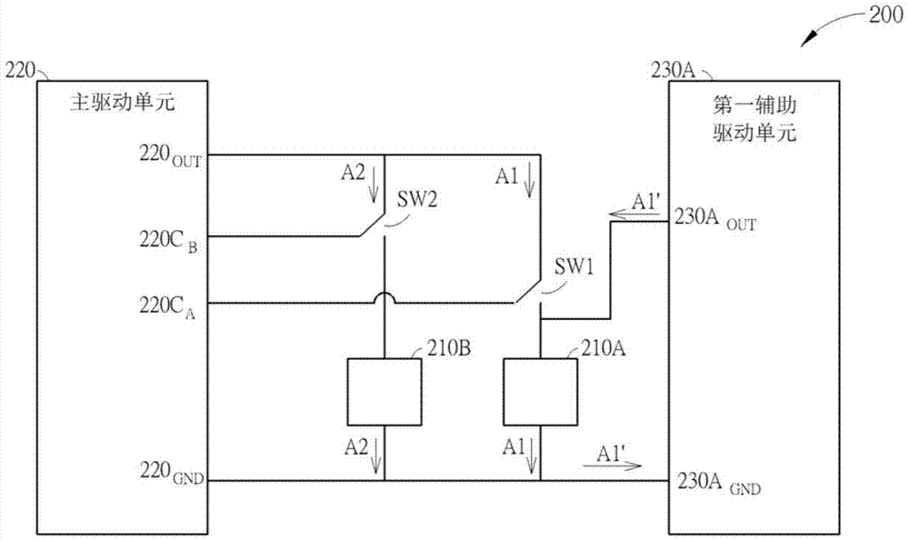
[0032] figure 2 A schematic diagram of an electronic device provided by an embodiment of the present invention, such as figure 2 As shown, the electronic device 200 includes a first light emitting module 210A, a second light emitting module 210B, a main driving unit 220 and a first auxiliary driving unit 230A. The first light-emitting module 210A and the second light-emitting module 210B can be light-emitting diodes, and can emit first light and second light respectively. The main driving unit 220 has an output terminal 220 OUT , the output terminal 220 OUT For selectively providing driving current to the first light emitting module 210A and the second light emitting module 210B, the main driving unit 220 has a first control terminal 220C A , the first control ter...


PUM


Abstract

A method and electronic device for increasing brightness. The present invention provides an electronic device, which includes: a first light emitting module, a second light emitting module, a main driving unit and a first auxiliary driving unit; the driving unit includes a first control terminal and a second control terminal, the The first control terminal is used to supply power to the first light-emitting module during the first period and stop supplying power to the first light-emitting module during the second period, and the second control terminal is used to light the second light-emitting module only during the second period The second light-emitting module stops supplying power to the second light-emitting module during the first period, so that the first light-emitting module emits first light during the first period and the second light-emitting module emits light during the second period. The second light: the first auxiliary driving unit is used to supply power to the first light-emitting module during the second period, so that the first light-emitting module emits fourth light during the second period.

Description

technical field [0001] The invention relates to an electronic device capable of emitting light, in particular to an electronic device capable of increasing brightness. Background technique [0002] Electronic devices need to provide multiple light sources to light up images, such electronic devices may be projectors or screens with backlights. These electronic devices usually require a control unit to control the light of different light sources to achieve the purpose of color mixing, such as figure 1 As shown, the electronic device 100 includes a main driving unit 120, switches SW1, SW2, SW3 and light emitting modules 110A, 110B and 110C, and the main driving unit 120 has a control terminal 120C A , 120C B with 120C C They are used to respectively control the switches SW1 , SW2 and SW3 to further control the power supply status of the light emitting modules 110A, 110B and 110C. The main driving unit 120 requires high energy consumption when driving the light-emitting mo...

Claims


Application Information

Patent Timeline
Patent Type & Authority Patents(China)
IPC IPC(8): H05B37/02
Inventor 陈启仁吕芳杰陈专助邹庆颖
Owner QISDA OPTRONICS (SUZHOU) CO LTD
Why Eureka
Try Eureka