High-speed moving target position and posture measurement method based on coding structured light

A technology for encoding structured light and high-speed motion, which is applied in the directions of measuring devices, photogrammetry/video metrology, surveying and navigation, etc., and can solve the problem of not being able to install characteristic markers on the surface of non-cooperative targets

Active Publication Date: 2015-12-23
DALIAN UNIV OF TECH
View PDF5 Cites 17 Cited by
  • Summary
  • Abstract
  • Description
  • Claims
  • Application Information

AI Technical Summary

Problems solved by technology

[0004] The technical problem to be solved by the present invention is to overcome the defects of the prior art and to invent a method for measuring the pose of a high-speed moving target based on coded structured light. This method adopts a high-speed measurement system composed of a monocular high-speed camera and a color projector The position and orientation measurement of high-speed moving targets in the field solves the accessibility problem that traditional measurement methods cannot install feature markers on the surface of non-cooperative targets and affect the accessibility of the measurement; The matching operation of the experimental model realizes the high-precision dynamic measurement of the pose information without any processing on the high-speed moving target; compared with the binocular pose measurement system, the structure is simple, the equipment investment is reduced, and the measurement is expanded. Field of view: solves the problem of accurately and quickly measuring the position and posture information of the target under the condition of large measurement field of view and high-speed motion of non-cooperative targets

Method used


Image

  • High-speed moving target position and posture measurement method based on coding structured light
  • High-speed moving target position and posture measurement method based on coding structured light
  • High-speed moving target position and posture measurement method based on coding structured light

Examples


Embodiment Construction

[0055] The specific embodiments of the present invention will be described in detail below in conjunction with the technical solutions and accompanying drawings.

[0056] The present invention adopts a color grating spatial coding pattern that combines a pseudo-random sequence of color stripes with a gray-scale grating phase; since the phase information cycle of the gray-scale grating pattern is difficult to restore in a single image, and the pseudo-random color fringe Sequential spatial coding makes full use of the color information of the stripe itself and its surroundings when coding the position of the stripe, and constitutes a unique code at the pixel level in a single image, which can realize dynamic measurement of a single image.

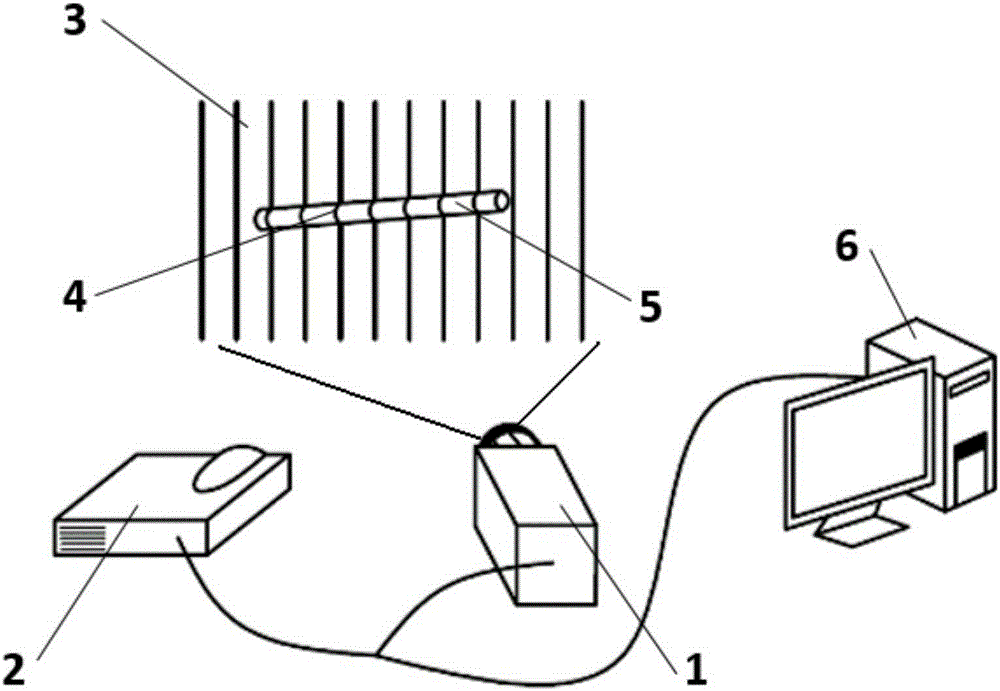
[0057] attached figure 1 It is a schematic diagram of a method for measuring the pose of a high-speed moving object based on color-coded structured light. A high-speed camera 1 is used to collect images of a high-speed moving target object 5...


PUM


Abstract

The invention provides a high-speed moving target position and posture measurement method based on coding structured light, belongs to the technical field of computer vision measurement, and relates to the large-visual-field and small-target high-speed moving target position and posture measurement method. The method includes the steps of projecting a colored grid line containing coding information to a measured area through a colored projector, continuously shooting structured light coding grid line patterns, deformed through moving object surface modulation, through a high-speed camera, achieving corresponding point matching of an imaging plane and a projection plane after digital image decoding to obtain phase position change information, reversely calculating the three-dimensional dynamic morphology of a high-speed moving object through system structure parameters, matching the measured point with a prior model established on the basis of to-be-measured geometrical parameters, and finally accurately measuring position and posture information of the high-speed moving object. The purpose of matching in stereoscopic vision is effectively achieved through a colored stripe pseudorandom sequence and gray scale grid line phase position combined mode. A measurement system is low in cost, simple in mechanism and easy to operate.

Description

technical field [0001] The invention belongs to the technical field of computer vision measurement, and relates to a method for measuring the spatial position and attitude of a non-cooperative high-speed moving target in a large field of view. Background technique [0002] Object pose information plays a very important role in the fields of aerospace, robot navigation, and automobile industry. In order to ensure the real-time controllable target pose under various working conditions, it is very necessary to measure the object pose. It also puts forward many new requirements for object pose measurement technology. Especially for the pose measurement of high-speed moving targets with a large field of view, in order to ensure the true restoration of working conditions, without any processing on the target object, the main problem to be solved at this stage is to quickly and accurately measure the target object pose information. [0003] At present, there are few studies on the...

Claims


Application Information

Patent Timeline
Patent Type & Authority Applications(China)
IPC IPC(8): G01C11/00
CPCG01C11/00
Inventor 刘巍陈玲贾振元刘惟肖马鑫
Owner DALIAN UNIV OF TECH
Why Eureka
Try Eureka