
Controller for air conditioner

Pending Publication Date: 2022-09-29
DENSO WAVE INC
View PDF1 Cites 0 Cited by
  • Summary
  • Abstract
  • Description
  • Claims
  • Application Information

AI Technical Summary

Benefits of technology

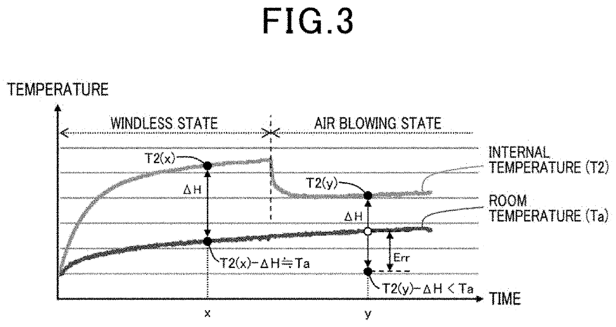
The patent is for a controller for an air conditioner that can accurately determine the temperature of a room by measuring the difference in heat between the heat source and the internal temperature of the machine. This means that changes in the temperature of the housing caused by other factors are removed, resulting in a more accurate measurement of the room temperature.

Problems solved by technology

However, there are other factors that affect the temperature measured by the temperature sensor in addition to the heat generation inside the housing.
As a result, when correction using the same correction value is performed in a state where an air flow is present and a state where an air flow is absent, the correction may be excessive in the state where an air flow is present.
Further, it is difficult to accurately determine the room temperature since the measured temperature itself changes between the state where an air flow is present and the state where an air flow is absent and an influence of air flow is practically difficult to accurately recognize.

Method used


Image

  • Controller for air conditioner
  • Controller for air conditioner
  • Controller for air conditioner

Examples


first embodiment

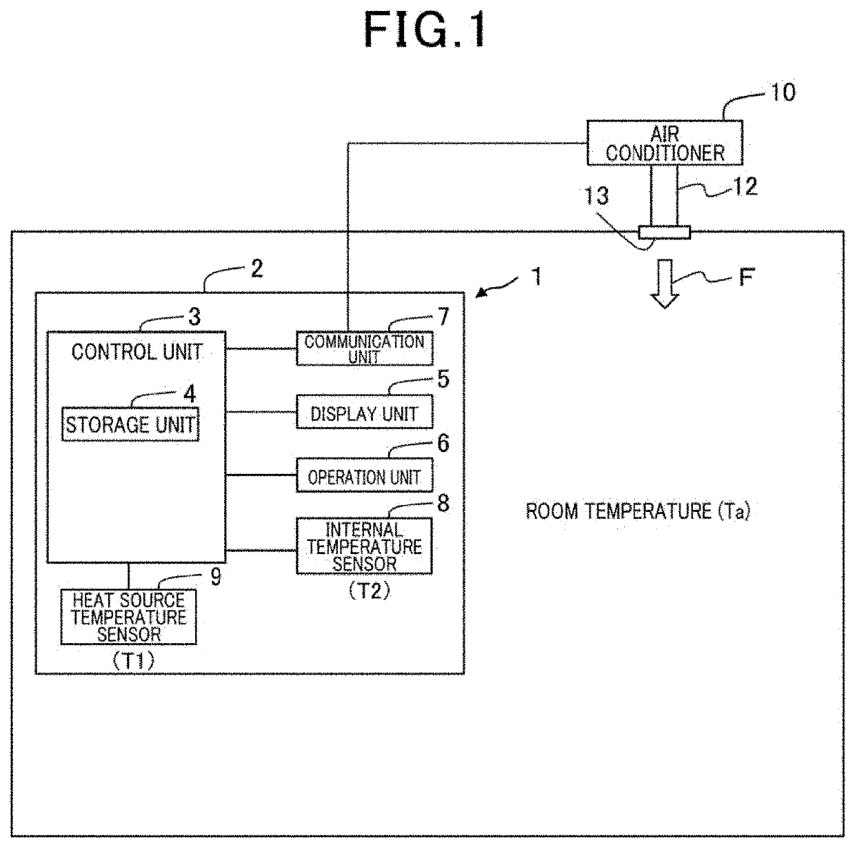
[0028]As shown in FIG. 1, a controller 1 of the present embodiment includes a housing 2, a control unit 3, a storage unit 4, a display unit 5, an operation unit 6, a communication unit 7, an internal temperature sensor 8, a heat source temperature sensor 9, and the like. The controller 1 is used to set a target temperature for an air conditioner 10 and display a room temperature (Ta). The configuration of the controller 1 shown in FIG. 1 is merely an example, and is not limited thereto.

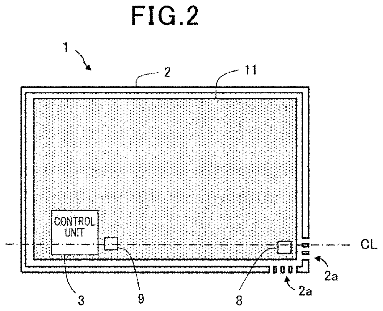
[0029]The housing 2 is formed, for example, in a generally rectangular thin box shape made of a resin material or the like, and is mounted on an installation surface on a wall or the like of a room to be air-conditioned, such as an office or a living room. In the present embodiment, the housing 2 is assumed to have a relatively small size. The relatively small size is assumed to have a side length of, for example, approximately less than 100 mm, and when an air flow occurs around the housing 2, the en...

second embodiment

[0074]The following description will be given of a second embodiment. The second embodiment is different from the first embodiment in that the heat source temperature used for determining an amount of increase in the internal temperature is corrected. Since the overall configuration and the flow of process by the controller 1 are substantially the same as those in the first embodiment, the following description will be given with reference to FIGS. 1 and 2.

[0075]The controllers 1, when they are the same products, are produced using the same types of electrical components. However, there may be individual differences among the electrical components that are used. For example, as shown in FIGS. 8A and 8B, a result of measuring the heat source temperatures of three controllers 1, which are referred to as G1, G2 and G3, under the test environment at the same temperature shows that there is a case where the heat source temperature measured for each controller 1 is different from the othe...


PUM


Abstract

A controller according to an embodiment of the present disclosure is a controller for an air conditioner that performs air-conditioning according to room temperature, the controller comprises: a housing; a heat source temperature sensor disposed inside the housing, the heat source temperature sensor being configured to measure a temperature of a heat source that generates heat during operation as a heat source temperature; an internal temperature sensor disposed inside the housing at a position away from the heat source, the internal temperature sensor being configured to measure a temperature inside the housing as an internal temperature; and a control unit that determines the room temperature using a temperature difference between the measured heat source temperature and the measured internal temperature.

Description

CROSS-REFERENCE TO RELATED APPLICATION[0001]This application is based on and claims the benefit of priority from earlier Japanese Patent Application No. 2021-53398 and No. 2021-53401 filed Mar. 26, 2021, the description of which is incorporated herein by reference.BACKGROUND OF THE INVENTIONTechnical Field of the Invention[0002]The present disclosure relates to a controller for use in controlling an air conditioner.Related Art[0003]It has been known that a temperature sensor that measures room temperature of a room to be air-conditioned is provided so that an air conditioner is controlled according to the room temperature measured by the temperature sensor. JP 2020-165632 A is an example of the related art.SUMMARY[0004]In such an air conditioner, the temperature sensor may be provided inside a housing of a controller. In this case, the temperature sensor measures a temperature inside the housing. The housing contains a heat source such as a microcomputer that generates heat during o...

Claims


Application Information

Patent Timeline
IPC IPC(8): F24F11/89
CPCF24F11/89F24F2110/10F24F11/63
Inventor AOKI, SHUNYAHATTORI, TORU
Owner DENSO WAVE INC
Learn More