Shock absorber

Inactive Publication Date: 2019-04-11
KYB CORP
View PDF0 Cites 2 Cited by
  • Summary
  • Abstract
  • Description
  • Claims
  • Application Information

AI Technical Summary

Benefits of technology

[0006]An object of the present invention is to provide a shock absorber

Problems solved by technology

In this case, a reciprocating pump is unsuitable and other kinds of pumps, such as a gear pump, are suitable.
However, a pump like the gear pump causes an internal leakage.
Therefore, the use of such a pump fails to accurately obtain a liquid amount supplied fro

Method used


Image

  • Shock absorber
  • Shock absorber
  • Shock absorber

Examples


Example

[0013]The following describes an embodiment of the present invention with reference to the drawings. Like reference numerals designate identical elements or corresponding components throughout some drawings.

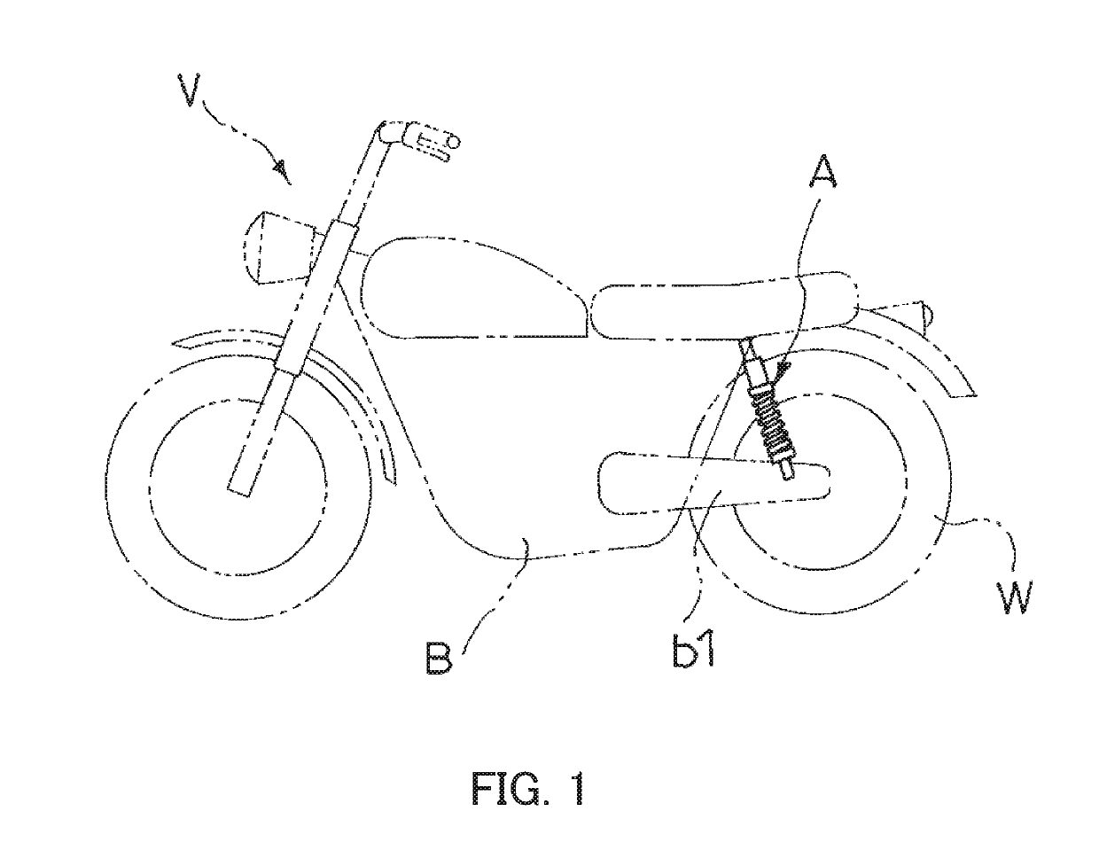
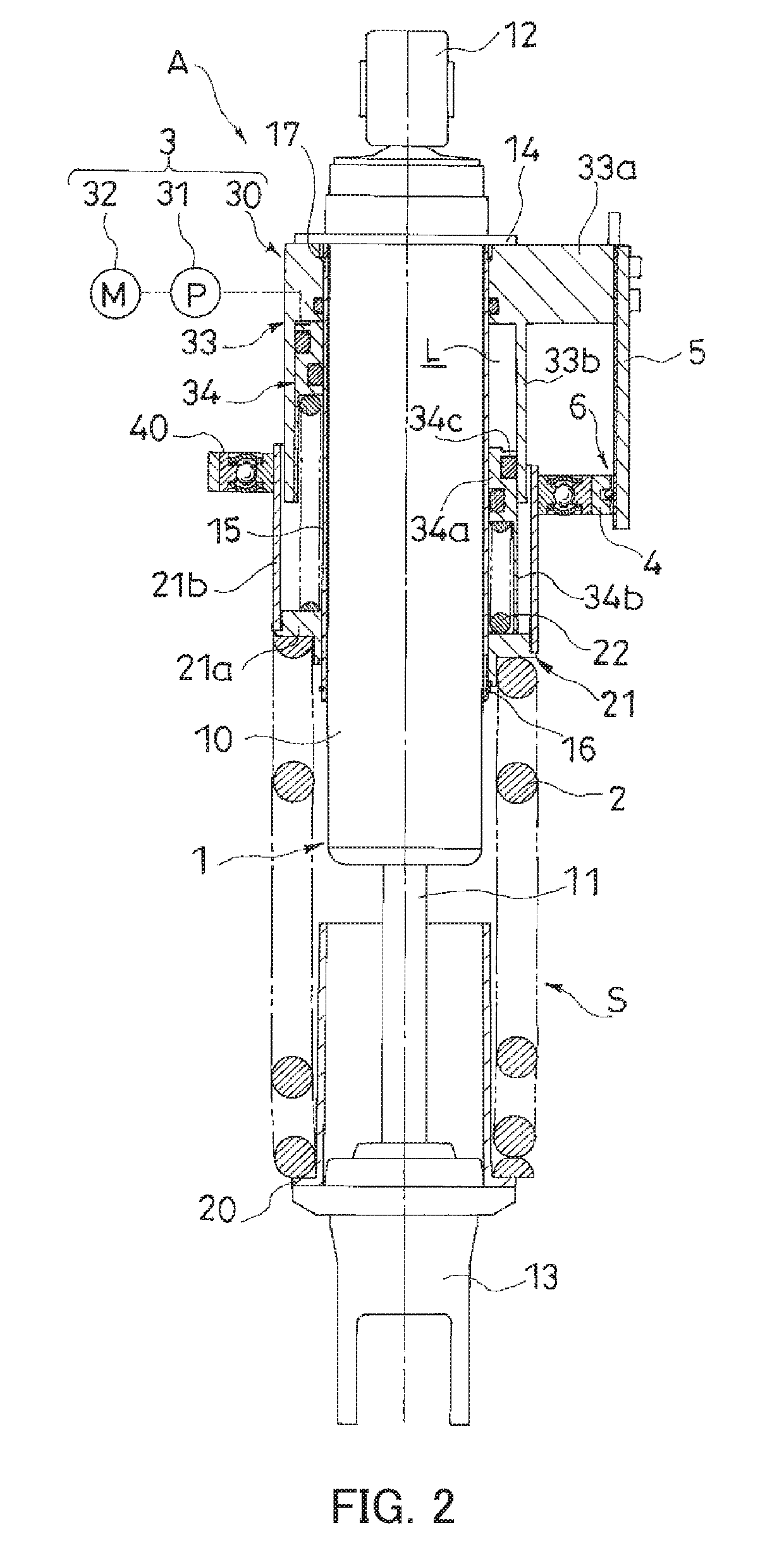
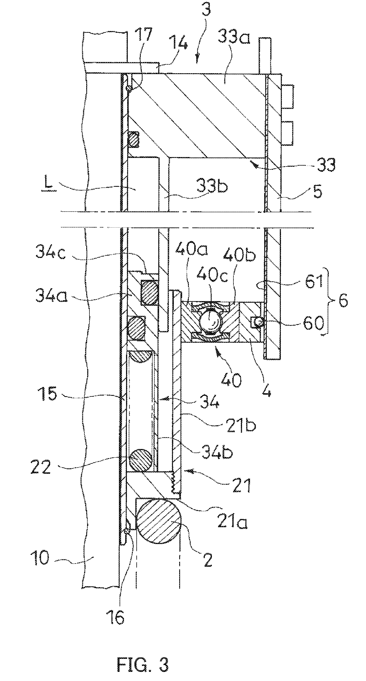
[0014]As illustrated in FIG. 1, a shock absorber A according to an embodiment of the present invention is disposed between a vehicle body B and a rear wheel W of a motorcycle V that is a vehicle. As illustrated in FIG. 2, the shock absorber A includes a shock absorber main body 1, a suspension spring 2, a spring bearing 20, a spring bearing 21, a jack 3, an auxiliary spring 22, an adapter 4, a rotation stop member 5, and a stroke sensor 6. The suspension spring 2 is disposed in an outer periphery of the shock absorber main body 1. The spring bearing 20 supports a lower end (an end portion at a lower side in FIG. 2) of the suspension spring 2. The spring bearing 21 supports an upper end (an end portion at an upper side in FIG. 2) of the suspension spring 2. The jack 3 adjusts a po...


PUM


Abstract

A shock absorber includes a suspension spring configured to bias the shock absorber main body in an extension direction; a spring bearing that supports one end of the suspension spring; a jack configured to change an axial position of the spring bearing; an adapter rotatably mounted on the spring bearing, the adapter being restricted to move in an axial direction with respect to the spring bearing; a rotation stop member mounted on the shock absorber main body to stop a rotation of the adapter; and a stroke sensor disposed between the adapter and the rotation stop member.

Description

TECHNICAL FIELD[0001]The present invention relates to a shock absorber.BACKGROUND ART[0002]Conventionally, a shock absorber is used for supporting a rear wheel of a saddle-ride type vehicle, such as a two-wheeled vehicle or a three-wheeled vehicle. The shock absorber disclosed in JP2010-149548A is configured such that a jack drives a spring bearing that supports one end of a suspension spring, such as a coiled spring, to adjust a vehicle height.[0003]Specifically, the jack in JP2010-149548A includes a housing, a piston, and a pump. The piston is movably inserted in this housing to form a liquid chamber in the housing. The pump supplies a liquid to the liquid chamber. This pump is a reciprocating pump including a single pump chamber. A liquid of a volume obtained by multiplying a piston cross-sectional area of the pump by a movement distance of the piston is supplied to the liquid chamber. In view of this, a liquid amount supplied to the liquid chamber is approximately accurately kno...

Claims


Application Information

Patent Timeline
IPC IPC(8): B60G15/06B62K25/10F16F9/56F16F9/46
CPCB60G15/062B62K25/10F16F9/56F16F9/46B60G2204/112B60G2400/252B60G15/065B60G2202/312B60G2300/12B60G2500/30F16F9/19F16F9/461
Inventor MOCHIZUKI, TAKAHISA
Owner KYB CORP
Why Eureka
Try Eureka