
A method of installing dirt collection tank for locomotive fuel tank

An installation method and a technology of a dirt collection tank, which are applied in the field of a dirt collection tank, can solve problems such as inconvenient installation and unfavorable weld detection, so as to avoid poor quality of welds, solve poor accessibility of weld welding and inspection, and effectively Good for quality control

Active Publication Date: 2017-08-25
CRRC ZIYANG CO LTD
View PDF5 Cites 0 Cited by
  • Summary
  • Abstract
  • Description
  • Claims
  • Application Information

AI Technical Summary

Problems solved by technology

[0002] At present, the traditional dirt collection tank of a locomotive is installed and fixed on the inside of the upper cover of the oil tank of the locomotive. The sewage pipe of the sewage tank is aligned with the sewage outlet of the outer plate of the main body of the fuel tank, which is very inconvenient to install, and the weld between the sewage collection tank and the upper cover plate is located inside the fuel tank body, which is not conducive to the later weld detection

Method used


Image

  • A method of installing dirt collection tank for locomotive fuel tank
  • A method of installing dirt collection tank for locomotive fuel tank
  • A method of installing dirt collection tank for locomotive fuel tank

Examples


Embodiment Construction

[0028] The present invention will be further described below in combination with specific embodiments and accompanying drawings.

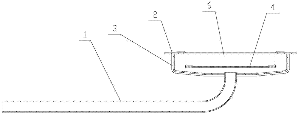
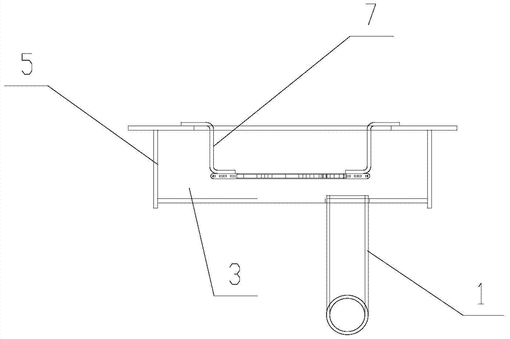
[0029] see Figure 1 to Figure 6 As shown, a sewage collecting tank for a locomotive oil tank includes a sewage pipe 1, a cover plate 2, a U-shaped coaming plate 3, a filter screen 4 and an end plate 5, and the front and rear ends of the U-shaped coaming plate 3 are connected to the end plate 5 to form a A tank body with an upper end opening, the bottom of the tank body is connected to the sewage pipe 1, the top of the tank body is installed with a cover plate 2, and an oil leakage hole 6 is arranged on the cover plate 2, and a filter screen 4 is hung and installed in the oil leakage hole 6 through a pendant 7, The filter screen 4 is fixedly connected to the bottom of the pendant 7, the cover plate 2 is welded and fixed on the fuel tank partition 8, and the sewage pipe 1 cooperates with the sewage outlet on the outer side wall 9 of the fuel tank. ...


PUM


Abstract

The invention discloses a dirt collection tank for a locomotive oil tank and an installation method, which comprises a sewage pipe, a cover plate, a U-shaped coaming plate, a filter screen and an end plate. The front and rear ends of the U-shaped coaming plate are connected to the end plates to form an upper opening The bottom of the tank is connected to the sewage pipe, the top of the tank is equipped with a cover plate, and an oil leakage hole is arranged on the cover plate, and a filter screen is installed in the oil leakage hole. The pipe fits into the drain port on the outer wall of the fuel tank. In the invention, the dirt collecting tank is first welded into a whole, which is convenient for process diversion of the dirt collecting tank, facilitates flaw detection and inspection of weld seams, and is beneficial to quality control. Then weld and fix the dirt collecting tank on the fuel tank body first, and finally install the upper cover of the fuel tank, so that the welding seam of the dirt collecting tank and the upper cover of the fuel tank is arranged on the outside of the fuel tank body, which is convenient for the welding seam of the upper cover of the fuel tank and the dirt collecting tank Welding is convenient for flaw detection of the weld. The invention can effectively solve the problem that the traditional dirt collecting tank is difficult to assemble in the closed cavity.

Description

technical field [0001] The invention relates to a dirt collection tank, in particular to a dirt collection tank for a locomotive oil tank. Background technique [0002] At present, the traditional dirt collection tank of a locomotive is installed and fixed on the inside of the upper cover of the oil tank of the locomotive. The sewage pipe of the sewage tank is aligned with the sewage outlet of the outer plate of the main body of the fuel tank, which is extremely inconvenient to install, and the weld between the sewage collection tank and the upper cover plate is located inside the fuel tank body, which is not conducive to later weld inspection. [0003] Therefore, how to solve the above technical problems has become an urgent problem for those skilled in the art. Contents of the invention [0004] The object of the present invention is to provide a kind of dirt collecting tank and installation method for the oil tank of a locomotive, which can completely solve the above-m...

Claims


Application Information

Patent Timeline
Patent Type & Authority Patents(China)
IPC IPC(8): B61C17/02
Inventor 景松柏吴凯叶萍陈强江太宏隆孝军吴振乾王富强伍华靳宁
Owner CRRC ZIYANG CO LTD
Learn More