Blocking elements for ball trap screen

A technology of blocking elements and screen tubes, applied in multiple fields of blocking elements

Active Publication Date: 2016-01-06
C Q M LTD
View PDF8 Cites 2 Cited by
  • Summary
  • Abstract
  • Description
  • Claims
  • Application Information

AI Technical Summary

Problems solved by technology

[0005] The inventor of the present case found that the multiple "T" type ball catchers currently used cannot achieve the purpose of collecting all the cleaning balls located in the system

Method used


Image

  • Blocking elements for ball trap screen
  • Blocking elements for ball trap screen
  • Blocking elements for ball trap screen

Examples


Embodiment Construction

[0025] The present invention is a plurality of blocking elements for enhancing the movement of the cleaning balls through the ball catch screens of the ball catcher in a closed fluid flow system.

[0026] The principles and operation of the blocking elements used in accordance with the present invention with catch screens may be better understood with reference to the accompanying drawings and the accompanying description.

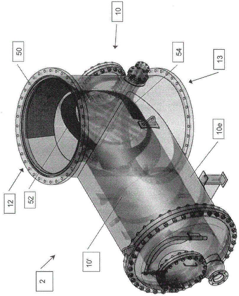
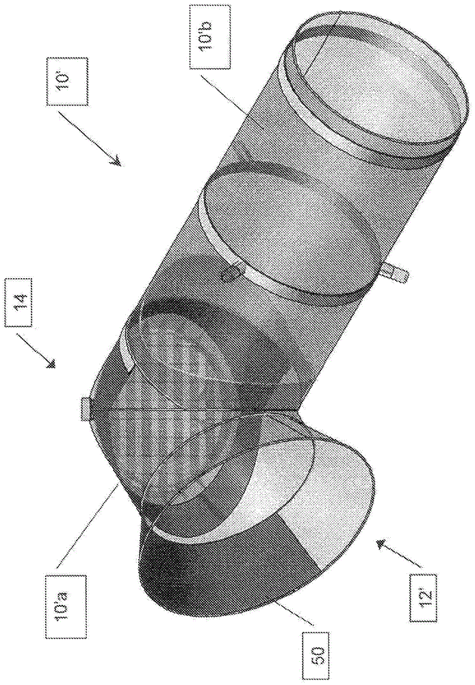
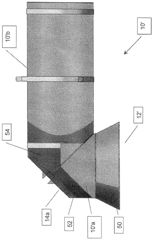
[0027] Now please refer to the attached picture, figure 1 A transparent view of a "T"-shaped ball catcher 2 is shown, which has a ball catcher housing 10 with a water inlet 12, a water outlet 13 and a ball catcher extension 10e. Also shown is a ball catch screen 10' deployed within the ball catch housing 10. It can be understood that, in such a plurality of ball catchers, the main fluid flow path is located at the water inlet 12, a water outlet 13 and guides the plurality of cleaning balls through a secondary fluid flow path to the Between the three in t...


PUM


Abstract

A ball trap screen for use with "T" type ball traps having a ball trap extension in which the ball trap screen includes a cone shaped inlet; an elbow, at least a portion of which includes a substantially planer solid area; a first screen section extending between the cone shaped inlet and the elbow; and a second screen section extending from the elbow into the ball trap extension; wherein at least a portion of the cone shaped inlet includes a solid cone blocking element, the first screen section includes a solid first screen blocking element and the second screen section includes a solid second screen blocking element. Also described are a ball trap for collecting cleaning balls, blocking elements for a ball trap screen and a method of enhancing the movement of the cleaning ball through the ball trap of a closed fluid flow system by blocking portions of a ball trap screen deployed within a ball trap housing so as to modify the fluid flow through the ball trap.

Description

technical field [0001] The present invention relates to a plurality of ball catchers for use in a heat exchanger cleaning system, and in particular, it relates to a plurality of ball catcher screens for use in enhancing movement of cleaning balls through said ball catchers Multiple blocking elements. Background technique [0002] It is known to collect the cleaning balls for cleaning closed fluid flow systems, such as heat exchangers in a balltrap, and then attract them from the balltrap to a collection Ball room. Ball catchers may be configured to extend at substantially any angle from the main flow duct. [0003] At present, it is increasingly popular to utilize a ball catcher extending at a 90 degree from the main fluid flow pipe, for example a ball catcher is often referred to as a "T" type ball catcher (such as "10" in the accompanying drawings). ). [0004] Such ball catchers are typically provided with a screen or screen element 100 extending from the input openin...

Claims


Application Information

Patent Timeline
Patent Type & Authority Applications(China)
IPC IPC(8): F28G1/12
CPCF28G1/12
Inventor 兹维·利夫尼莫提·凯伦欧麦·利夫尼乌迪·史柏尼
Owner C Q M LTD
Why Eureka
Try Eureka