All-fiber Fourier transform Raman spectrometer

A technology of Raman spectrometer and optical fiber Fu, which is applied in the field of spectrometer to achieve the effect of small overall volume, stable and reliable system, and fewer components

Inactive Publication Date: 2016-01-13
CHINA ELECTRONIC TECH GRP CORP NO 38 RES INST
View PDF0 Cites 6 Cited by
  • Summary
  • Abstract
  • Description
  • Claims
  • Application Information

AI Technical Summary

Problems solved by technology

[0004] The purpose of the present invention is to provide an all-fiber Fourier transform Raman spectrometer for the miniaturization of existing Fourier transform Raman spectrometers

Method used


Image

  • All-fiber Fourier transform Raman spectrometer
  • All-fiber Fourier transform Raman spectrometer
  • All-fiber Fourier transform Raman spectrometer

Examples


Embodiment 1

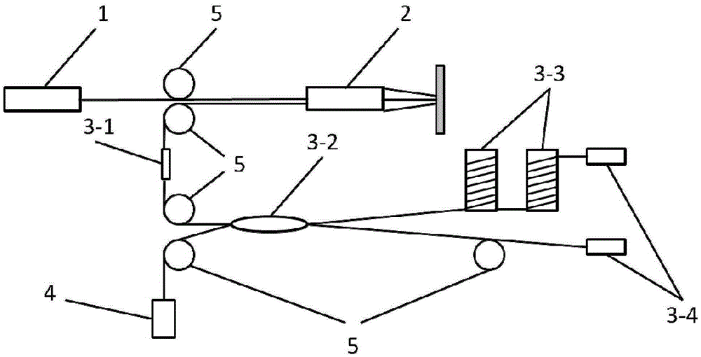
[0029] see figure 1 , the all-fiber Fourier transform Raman spectrometer of this embodiment includes a laser 1, a fiber Raman probe 2, an all-fiber double-beam interference system, a photomultiplier tube 4, and several transmission fibers 5. These transmission fibers 5 can be used to realize device correlation among the laser 1 , the fiber Raman probe 2 , the all-fiber double-beam interference system, and the photomultiplier tube 4 .

[0030] The laser 1 irradiates the sample 6 through the fiber optic Raman probe 2 and forms Raman scattered light. The Raman scattered light is collected by the fiber optic Raman probe 2 and enters the all-fiber double-beam interference system to form two paths of interference light. The optical path of one path of light is modulated by the phase modulator 3-3 in the all-fiber double-beam interference system, and the modulated interference light is output to the photomultiplier tube 4 to be converted into an electrical signal.

[0031] The fiber...

Embodiment 2

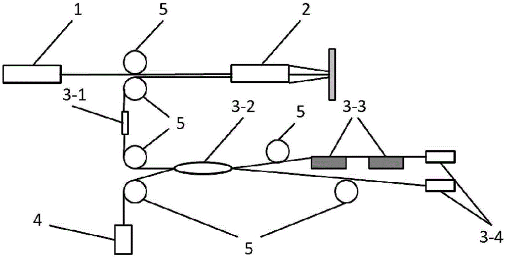
[0038] see figure 2 , the difference between embodiment 2 and embodiment 1 is: the phase modulator 3-3 of embodiment 2 is a piezoelectric ceramic micro-displacement device, adopts the form that the optical fiber is pasted on its surface, and the driving voltage is added to the piezoelectric ceramic micro-displacement device Come up to adjust the fiber length. Embodiment 2 has the beneficial effects of Embodiment 1.

Embodiment 3

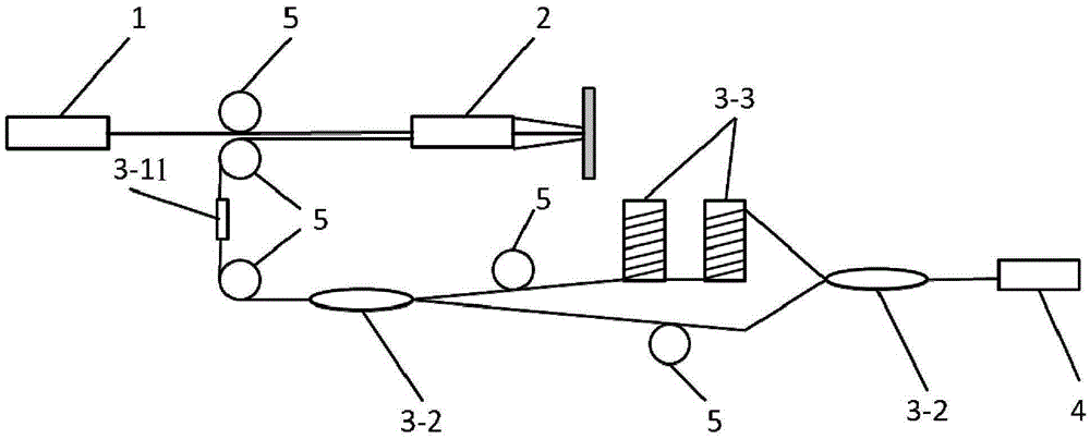
[0040] see image 3 The difference between embodiment 2 and embodiment 1 is that the fiber optic double-beam interference system of embodiment 2 uses a fiber Mach-Zehnder interferometer instead of a fiber Michelson interferometer.

[0041] The fiber Mach-Zehnder interferometer includes a fiber depolarizer 3-11, a pair of fiber 3dB couplers 3-2, and a group of phase modulators 3-3. The Raman scattered light first passes through the optical fiber depolarizer 3-11, and then enters the two arms of the optical fiber Mach-Zehnder interferometer formed by a pair of optical fiber 3dB coupler 3-2 two-way optical fiber fusion, wherein one arm is wound On a group of piezoelectric ceramic columns 3-3, apply a driving voltage to this group of piezoelectric ceramic columns 3-3, and the two beams of light in the two arms interfere at the other optical fiber 3dB coupler 3-2 to output an optical path difference The modulated interference light, the modulated interference light with the optica...


PUM


Abstract

The invention discloses an all-fiber Fourier transform Raman spectrometer, which includes transmission fibers, a laser, a fiber Raman probe, an all-fiber dual-beam interference system, and a photomultiplier. The laser, the fiber Raman probe, the all-fiber dual-beam interference system and the photomultiplier are associated with each other by means of the transmission fibers. The laser is irradiated on a sample through the fiber Raman probe and forms Raman diffusion light. The Raman diffusion light is collected by the fiber Raman probe and enters the all-fiber dual-beam interference system, and therefore two paths of interference light are formed. One light path of the two paths of interference light is modulated by a phase modulator in the all-fiber dual-beam interference system, and the modulated interference light is output to the photomultiplier and converted into an electric signal. Fourier transform of Raman spectrum is achieved and then spectrum demodulation is realized by means of the all-fiber dual-beam interference system, and dual-beam light path difference modulation is performed by an all-fiber phase modulator. The all-fiber Fourier transform Raman spectrometer, becoming miniature, is high in resolution, high in signal to noise ratio, wide in spectrum scope and low in cost.

Description

technical field [0001] The invention relates to a spectrometer, in particular to an all-fiber Fourier transform Raman spectrometer. Background technique [0002] The Fourier transform Raman spectrometer is based on the basic principle of Fourier transform spectroscopy, using the Fourier transform correspondence between the interferogram and the spectrogram, by measuring the interferogram, and performing Fourier transform on the interferogram to measure Spectrum. Compared with dispersive Raman spectrometers, Fourier transform Raman spectrometers have the advantages of high throughput, high sensitivity, high resolution, high signal-to-noise ratio, and anti-fluorescence spectral interference, and are widely used. However, because the traditional Fourier transform spectrometer includes a collimation system, a spectroscopic system and a detection and receiving system, it is bulky and expensive, which is not conducive to the popularization of the product. [0003] In recent year...

Claims


Application Information

Patent Timeline
Patent Type & Authority Applications(China)
IPC IPC(8): G01J3/44G01J3/45
Inventor 贺胜男武帅
Owner CHINA ELECTRONIC TECH GRP CORP NO 38 RES INST
Why Eureka
Try Eureka