Coil winding device and winding method thereof

A winding device and winding technology, which is applied in the direction of electromechanical devices, manufacturing motor generators, electrical components, etc., can solve the problem that flat winding machines cannot perform flat winding coils, etc., so as to reduce equipment procurement investment, save scientific research and production costs , Simple and convenient operation

Active Publication Date: 2016-01-13
CSR ZHUZHOU ELECTRIC CO LTD
View PDF9 Cites 0 Cited by
  • Summary
  • Abstract
  • Description
  • Claims
  • Application Information

AI Technical Summary

Problems solved by technology

[0008] The technical problem to be solved by the present invention is to provide a winding device and a winding method for the deficiency that existing flat winding machines cannot carry out edgewise winding coils, which can realize edgewise winding on ordinary flat winding winding machines and make edgewise winding coils. Coil

Method used


Image

  • Coil winding device and winding method thereof
  • Coil winding device and winding method thereof

Examples


Embodiment 1

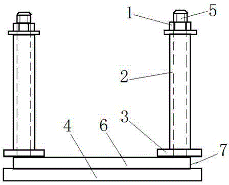
[0024] As shown in the drawings, a winding device for an edgewise coil includes a base 4 , a step 6 , a pressing plate 3 , a screw 5 , a sleeve 2 and a nut 1 . The base 4 is a long ring, and the edge of the upper plane is provided with a concave step 6, and the lower plane is fixedly installed on the rotary disk of the ordinary flat winding winding machine, and the rotary disk drives the base to rotate, and the coil winding is realized under manual operation. Four screw rods 5 are arranged at the corners of the base 4 , the sleeve 2 passes through the screw rods 5 , and the rear end can be fastened with a nut 1 . The pressing plate 3 is provided with a U-shaped notch, and the pressing plate 3 is clamped on the screw rod 5, and can also be taken out flexibly. The pressing plate 3 is annular, and the number is 3. It cooperates with the step 6 of the base 4 to form a limiting groove 7, and the flat copper wire is limited by the limiting groove 7 during operation. The front end o...

Embodiment 2

[0027] The basic structure of the second embodiment is the same as that of the first embodiment, except that the base 4 is rectangular, and the number of the pressing plates 3 is four, and each screw 5 is pressed with a fixed sleeve 2, and each fixed sleeve 2 A pressing plate 3 is pressed below, and the pressing plate 3 is rectangular. There is a slot on the pressing plate 3 , and the slot is locked on the screw rod 5 , and the pressing plate 3 is tightened and fixed by the fixing sleeve 2 through the nut 1 sleeved on the screw rod 5 .

[0028] The winding method is the same as that of Embodiment 1, and will not be described here again.


PUM


Abstract

The invention provides a winding device and winding method of a flat coil. The winding device comprises a base, a step, pressing plates, screw rods, sleeves and nuts; the base is in the shape of a long ring or a rectangle; the edge of the upper plane of the base is provided with the recessed step; the lower plane of the base is fixedly installed on a rotary disk of an ordinary flat winding machine; the corners of the base are provided with four screw rods; the sleeves pass through the screw rods; the rear ends of the sleeves are fastened through the nuts; the pressing plates are provided with U-shaped gaps which can be clamped onto the screw rods; the pressing plates are circular or rectangular and are matched with the step of the base, so that limiting grooves can be formed; and the front ends of the sleeves press on the pressing plates. With the winding device and winding method of the invention adopted, edgewise winding can be performed on the ordinary flat winding machine, and an edgewise wound coil can be produced, and equipment purchase investment can b reduced, and scientific research and production cost can be decreased, and operation is simple and convenient.

Description

technical field [0001] The invention relates to a manufacturing method and device for a motor component, in particular to a winding device for an edgewise coil and a winding method thereof, which are mainly used for winding the edgewise coil. Background technique [0002] Flat copper wires are wound into coils in two ways: flat winding and flat winding. Generally, flat winding machines and flat winding machines are used to wind flat winding coils and flat winding coils respectively. Compared with the flat winding machine, the structure of the flat winding machine is complex, and the investment in equipment procurement is also relatively large. Especially in the trial production stage of the coil, people hope that the flat wound coil can also be wound on the common flat winding machine. [0003] Through the patent search, no patent literature report on the same technology as the invention was found, and the patents related to the present invention mainly include the followin...

Claims


Application Information

Patent Timeline
Patent Type & Authority Applications(China)
IPC IPC(8): H02K15/04
Inventor 曹保平赵忠胜邓灿华钟军周杏军
Owner CSR ZHUZHOU ELECTRIC CO LTD
Why Eureka
Try Eureka