a smart seat
A seat and intelligent technology, which can be used in patient chairs or special transportation tools, vehicle ambulance, medical transportation, etc., and can solve problems such as high price, large structure, and complexity
- Summary
- Abstract
- Description
- Claims
- Application Information
AI Technical Summary
Problems solved by technology
Method used
Image
Examples
Embodiment 1
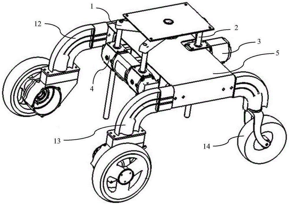
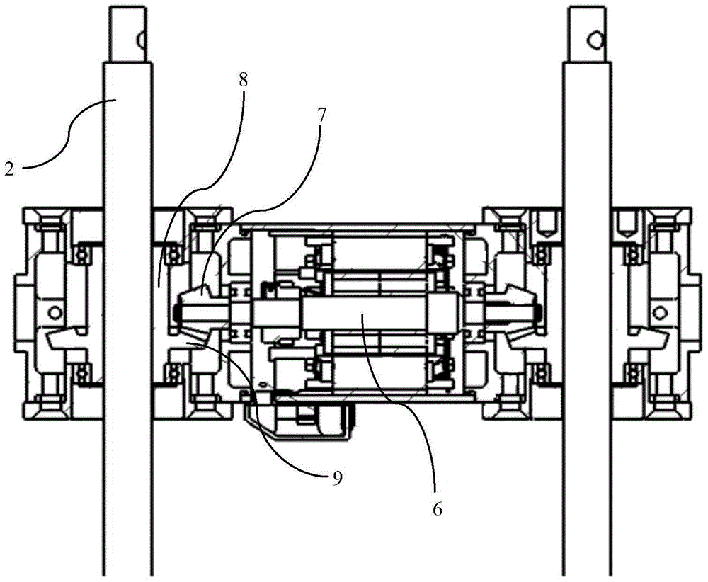
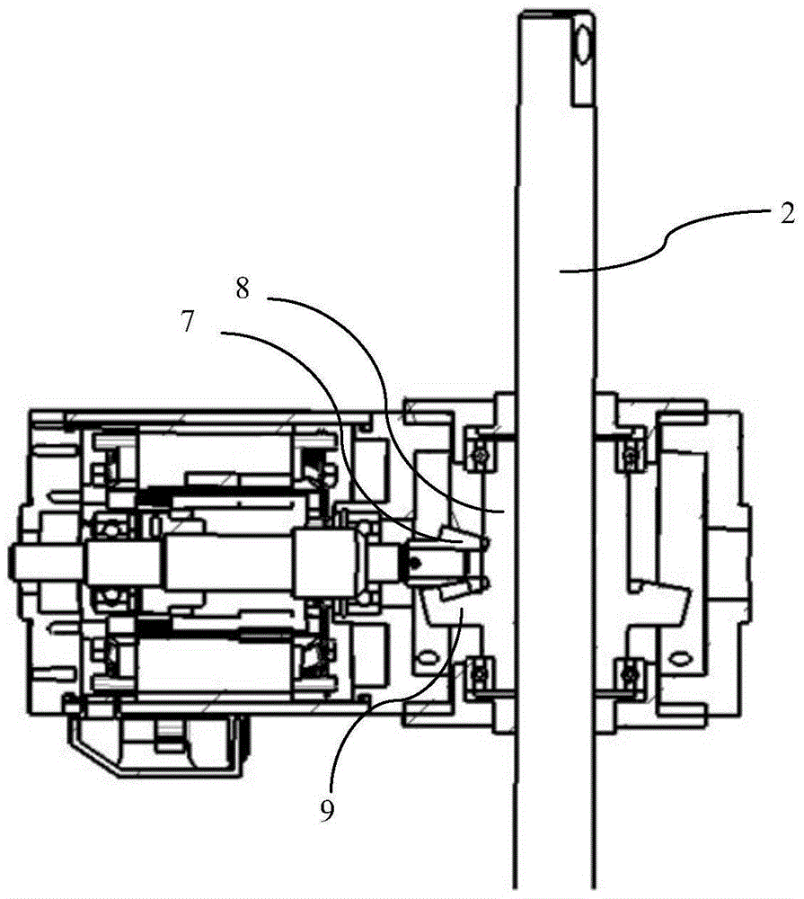
[0028] Such as figure 1 The smart seat shown includes a Y-shaped level adjustment bracket 1, an adjustment lever 2, a level sensor and a controller. The seat seating surface is the front and the backrest surface of the seat is the rear. The adjustment lever 2 has Three, one in front of the seat and two behind the seat. The upper end of the adjustment rod located in front of the seat is rotatably connected with the horizontal adjustment bracket 1, and the lower end of the adjustment rod located in front of the seat is connected with the first motor 3 and is driven up and down by the first motor 3. In this embodiment The first motor 3 is a single-axis motor. The upper ends of the two adjustment rods located behind the seat are fixedly connected with the horizontal adjustment bracket 1, and the lower ends are connected with the second motor 4 and are driven up and down by the second motor 4. In this embodiment, the second motor 4 is a biaxial motor. The single-axis motor and the ...
Embodiment 2
[0032] Such as Figure 6-10 As shown, the present invention also provides a smart seat capable of realizing front and rear and left and right self-balancing at the same time. The difference from Embodiment 1 is that the second motor 4 located behind the seat has two independent motors. , Two adjusting rods are connected to two independent motors and driven up and down by the motors. Both independent motors can rotate in the front and rear directions; the horizontal adjustment bracket 1 connected to the upper ends of the three adjusting rods is a T-shaped bracket, The two ends of the beam have sliding grooves 10, the upper ends of the two adjusting rods located at the rear can be rotatably connected in the sliding grooves 10, and the position of the connection point can slide in the sliding groove 10; The upper end of the rod and the free end of the longitudinal beam of the T-shaped bracket are connected by a connecting shaft 11, which can rotate left and right relative to the T...
PUM
 Abstract
Description
Claims
Application Information
 - R&D
- Intellectual Property
- Life Sciences
- Materials
- Tech Scout
- Unparalleled Data Quality
- Higher Quality Content
- 60% Fewer Hallucinations
Browse by: Latest US Patents, China's latest patents, Technical Efficacy Thesaurus, Application Domain, Technology Topic, Popular Technical Reports.
© 2025 PatSnap. All rights reserved.Legal|Privacy policy|Modern Slavery Act Transparency Statement|Sitemap|About US| Contact US: help@patsnap.com


