Bicycle control device, motor assist bicycle, and motor control method
A control device, bicycle technology, applied in the direction of bicycle control system, bicycle, bicycle accessories, etc.
- Summary
- Abstract
- Description
- Claims
- Application Information
AI Technical Summary
Problems solved by technology
Method used
Image

Examples
no. 1 approach
[0038] refer to Figure 1 to Figure 5 The bicycle control device will be described.
[0039] In the following description, "left side" means the left-hand side of the user riding on the power-assisted bicycle (bicycle), and "right side" means the right-hand side of the user riding on the power-assisted bicycle. "Front" indicates the forward direction of the power-assisted bicycle. "Rear" indicates the reverse direction of the electric assist bicycle.
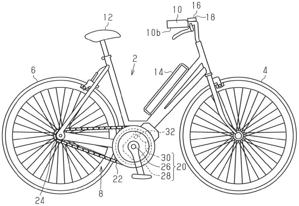
[0040] figure 1 In , an example of a power-assisted bicycle provided with a bicycle control device is shown.
[0041] The power-assisted bicycle includes a frame 2, a pair of wheels (a front wheel 4 and a rear wheel 6) rotatably mounted on the frame 2, a drive mechanism 8 for driving the rear wheel 6, and a drive mechanism 8 for changing the direction of the front wheel 4. The handlebar 10, the seat 12, the battery 14, the operation part 16 and the display part 18.
[0042] The operation unit 16 and the display unit 18 are ...
no. 2 approach
[0100] refer to Figure 6 , the control unit 32 of another embodiment will be described. The control unit 32 of the present embodiment has the same configuration as the control unit 32 shown in the first embodiment. In the following description, the corresponding components to those of the control unit 32 shown in the first embodiment are denoted by the same reference numerals for each component.
[0101] The control unit 32 of the present embodiment differs from the control unit 32 of the first embodiment in the mode switching process executed. In particular, the processing regarding the first operation switch 42 is different. Since the processing of the second operation switch 44 is the same as the mode switching processing in the first embodiment, description thereof will be omitted. Figure 6 followed by the "A" shown in Figure 5 "A". Hereinafter, processing related to the first operation switch 42 will be described.
[0102] In the control unit 32 of this embodimen...
no. 3 approach
[0112] refer to Figure 7 , and another embodiment of the operation unit 16 and the display unit 18 will be described. Hereinafter, the same components as those of the operation unit 16 and the display unit 18 shown in the first embodiment are denoted by the same reference numerals, and description thereof will be omitted. In addition, in the first embodiment, the input unit 34 is provided independently of other devices, but in the present embodiment, a part of the function of the operation unit 16 as the input unit 34 is provided in the shift operation unit 62 .
[0113] The operation unit 16 has a second operation switch 44 and a first operation switch 42 as the input unit 34 . The second operation switch 44 and the first operation switch 42 have the same functions as those of the second operation switch 44 and the first operation switch 42 shown in the first embodiment, and the operation mode can be changed, but they cannot be driven in the walking mode. Or stop the motor...
PUM
 Abstract
Description
Claims
Application Information
 - R&D
- Intellectual Property
- Life Sciences
- Materials
- Tech Scout
- Unparalleled Data Quality
- Higher Quality Content
- 60% Fewer Hallucinations
Browse by: Latest US Patents, China's latest patents, Technical Efficacy Thesaurus, Application Domain, Technology Topic, Popular Technical Reports.
© 2025 PatSnap. All rights reserved.Legal|Privacy policy|Modern Slavery Act Transparency Statement|Sitemap|About US| Contact US: help@patsnap.com