
Wall-mounted air conditioner indoor unit

An indoor unit and wall-mounted technology of an air conditioner, which is applied to airflow control elements and other directions, can solve the problems of small air swept range of the air outlet structure, and achieve the effect of improving the effect of left and right air guiding, uniform room temperature, and improving the effect of upper and lower air guiding.

Active Publication Date: 2016-01-27
WUHAN REFRIGERATION EQUIP OF MIDEA GROUP
View PDF7 Cites 19 Cited by
  • Summary
  • Abstract
  • Description
  • Claims
  • Application Information

AI Technical Summary

Problems solved by technology

[0005] The main purpose of the present invention is to solve the technical problem in the prior art that the air outlet structure of the indoor unit of the wall-mounted air conditioner has a small sweeping range

Method used


Image

  • Wall-mounted air conditioner indoor unit
  • Wall-mounted air conditioner indoor unit
  • Wall-mounted air conditioner indoor unit

Examples


Embodiment approach

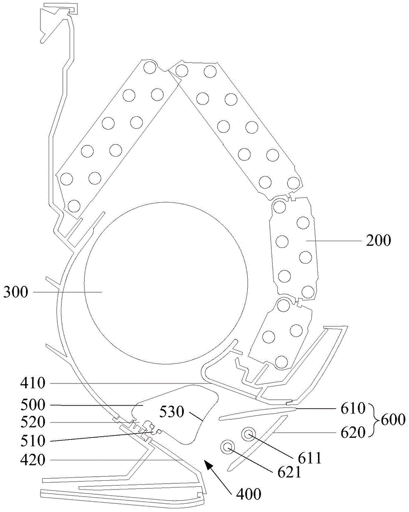
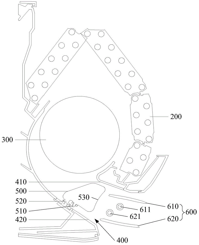
[0035] figure 2 The first embodiment of the upper wind deflector 610 and the lower wind deflector 620 is shown. In this embodiment, the width of the upper wind deflector 610 is equal to the width of the lower wind deflector 620, wherein the lower wind deflector 620 is closed At the same time, the air outlet 400 is covered, and the upper air deflector 610 is covered by the lower air deflector 620 in the air outlet 400. The upper air deflector 610 and the lower air deflector 620 are in a closed state, so the structure of the air deflector 600 is more It is compact and occupies less internal space of the air outlet 400 when closed. In addition, the outer surface of the lower air deflector 620 is arc-shaped, and when the lower air deflector 620 is closed, the outer surface of the lower air deflector 620 and the front panel (not shown in the figure) of the indoor unit body make a smooth transition, Therefore, the overall unity and aesthetic appearance of the indoor unit of the wa...


PUM


Abstract

The invention discloses a wall-mounted air conditioner indoor unit comprising an indoor unit body, an air outlet arranged in a lower portion of the indoor unit body, a blinds assembly arranged in the air outlet, an air guide plate support, and an air guide plate pivoted with the air guide plate support; the blinds assembly is arranged on an inner side of the air guide plate; the air guide plate comprises an upper air guide plate and a lower air guide plate independently swinging; the upper air guide plate is arranged close to an upper side wall of the air outlet; the lower air guide plate is arranged close to a lower side wall of the air outlet; when the air guide plate closes, the upper air guide plate or the lower air guide plate can cover the air outlet. The wall-mounted air conditioner indoor unit can enlarge an air supply scope, can improve the air conditioner usage comfort level, and the temperature in the room is more uniform.

Description

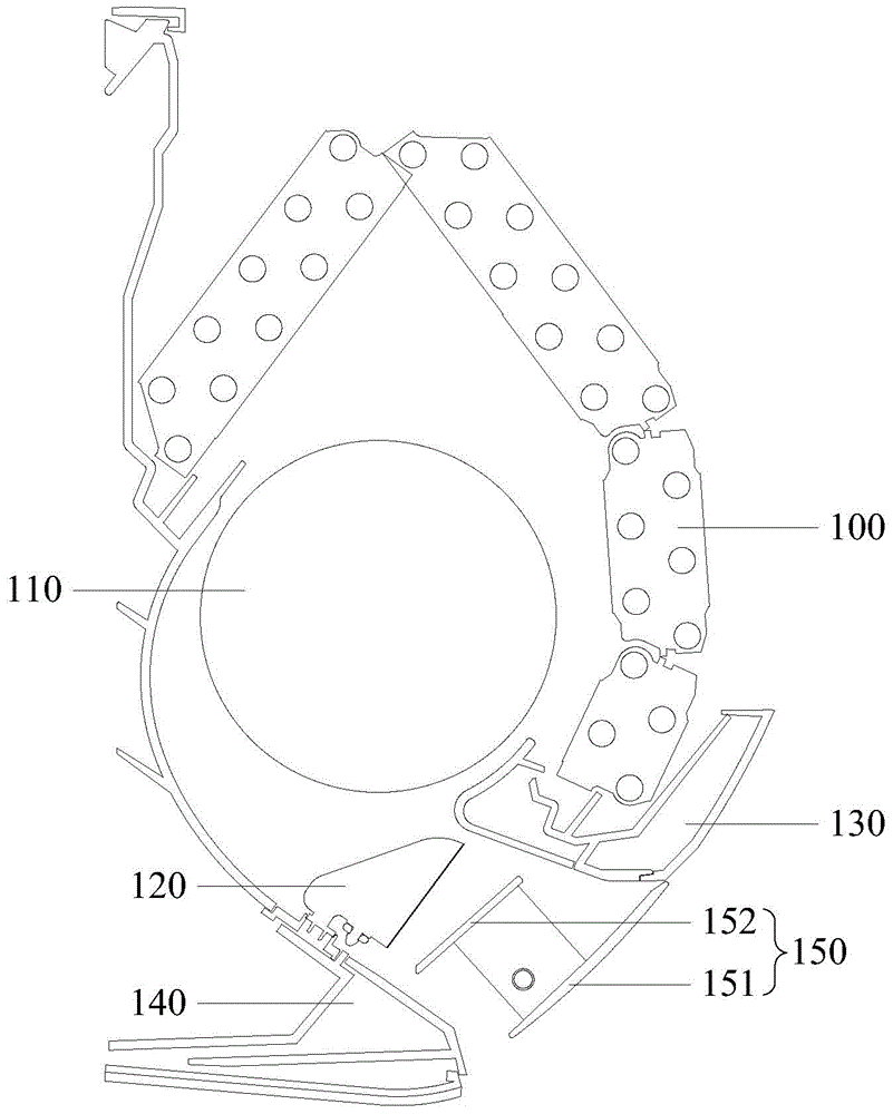
technical field [0001] The invention relates to the technical field of refrigeration, in particular to an indoor unit of a wall-mounted air conditioner. Background technique [0002] see figure 1 , the existing wall-mounted air conditioner indoor unit includes a housing, an evaporator 100 located in the housing, a wind wheel 110, a louver 120 located at the lower part of the housing, an air deflector bracket (not shown in the figure), an upper air outlet plate 130 , the lower air outlet plate 140 , and the air deflector 150 pivotally connected with the air deflector bracket. Wherein, an air outlet is formed between the upper air outlet plate 130 and the lower air outlet plate 140, the louvers 120 and the air guide plate 150 are located between the upper air outlet plate 130 and the lower air outlet plate 140, and the louvers 120 and the upper air outlet plate 130 and / or the lower air outlet plate 140 are pivotally connected and located inside the air deflector 150 . [00...

Claims


Application Information

Patent Timeline
Patent Type & Authority Applications(China)
IPC IPC(8): F24F13/10
Inventor 华龙姜风华李永镇谭周衡易万权
Owner WUHAN REFRIGERATION EQUIP OF MIDEA GROUP
Learn More