
An Automatic Cutting Mechanism for Side Gate of Laminated Injection Mold

An injection mold and side gate technology, which is applied in the field of automatic side gate removal mechanism, can solve the problems of high precision control requirements, low appearance quality, complex mold mechanism, etc., and achieves simple overall structure, saving injection cycle, precision Effects with low control requirements

Active Publication Date: 2017-09-26
QINGDAO HAIER MOLDS
View PDF6 Cites 0 Cited by
  • Summary
  • Abstract
  • Description
  • Claims
  • Application Information

AI Technical Summary

Problems solved by technology

[0004] 1. Manual removal, poor pruning quality, low appearance quality after pruning, high labor cost and low efficiency
[0005] 2. The gate is cut out in the mold by driving the cutter device through the oil cylinder, but the cost of the oil cylinder is high and the requirements for precision control are high
[0006] 3. The injection molding machine drives the ejector plate, and the cutter is fixed on the ejector plate to realize the removal of the gate in the mold. Not only is the mold mechanism complicated, but also it needs to be ejected in steps (two ejections), and the production efficiency is low.

Method used


Image

  • An Automatic Cutting Mechanism for Side Gate of Laminated Injection Mold
  • An Automatic Cutting Mechanism for Side Gate of Laminated Injection Mold
  • An Automatic Cutting Mechanism for Side Gate of Laminated Injection Mold

Examples


Embodiment Construction

[0030] The present invention will be further described in detail below in conjunction with the drawings and specific embodiments:

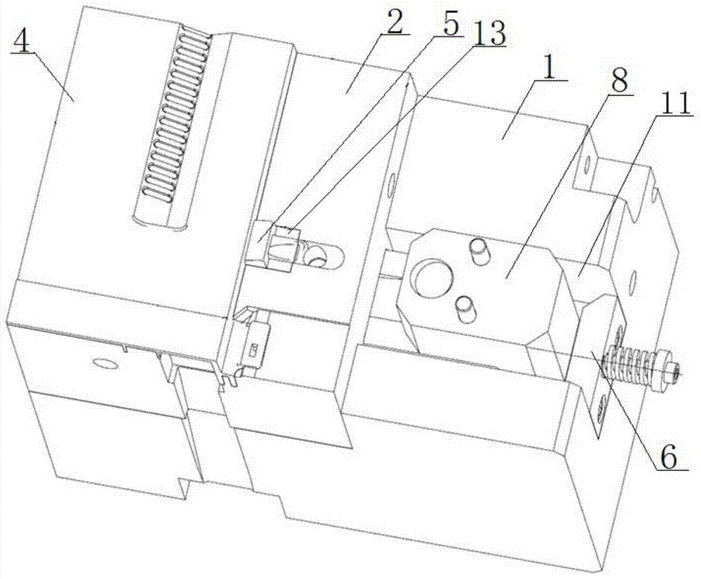
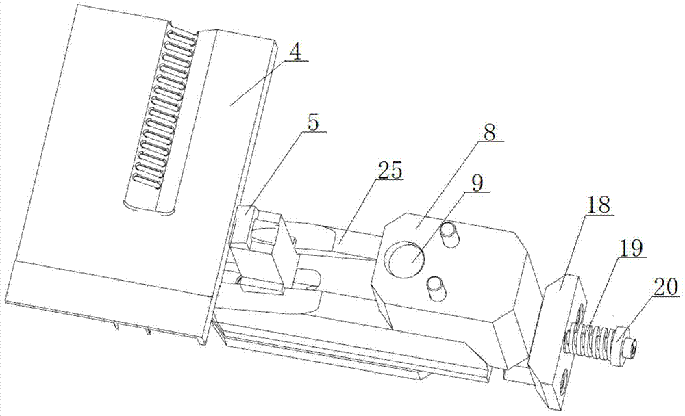
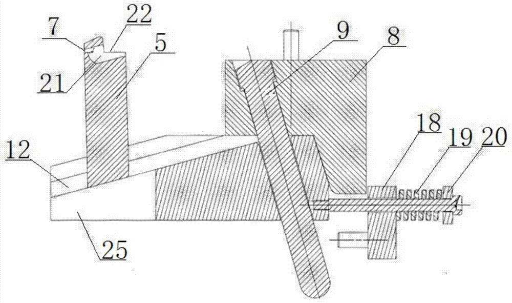
[0031] Such as Figure 1 to Figure 7 As shown, the present invention provides a laminated injection mold side gate automatic cutting mechanism, including a front mold (not shown in the figure) and a rear mold 1. The front mold and the rear mold 1 are provided with front mold molding inserts (Not shown in the figure), the back mold forming insert 2, the runner 3, the front mold forming insert and the rear mold forming insert 2 are fixedly installed on the front mold and the rear mold 1 by screws, and the front mold forming insert After being matched with the back mold molding insert 2 to form a cavity (not shown in the figure), the hot melt plastic enters the cavity through the runner 3, and forms a plastic product 4 after cooling. Under the action of the ejection mechanism, the back mold 1 Separate from the front mold and take out the product 4.

[0...


PUM


Abstract

The invention relates to a side gate automatic cutting mechanism of a laminated injection mold, comprising a front mold and a rear mold, on which a front mold forming insert, a rear mold forming insert, a mold cavity and a flow channel are arranged. channel, a shear block is provided between the runner and the cavity, the top of the shear block has a side gate matching with the runner, the shear block is connected to a set of lifting mechanism, the The shear block cuts and separates the gate and the product through the lifting mechanism. The invention cooperates the oblique guide column in the mold with the sliding base and the shear block to realize the automatic removal of the gate when the mold is opened, which saves the injection molding cycle, and has a stable and reliable structure and improves production efficiency. The gate is cut off at the same time as the mold is opened by mechanical movement, which does not require the drive of the oil cylinder in the prior art. The overall structure is very simple, the cost is greatly reduced, and the requirements for precision control are relatively low.

Description

Technical field [0001] The invention relates to an injection mold, in particular to a side gate automatic cutting mechanism used on a laminated injection mold, and belongs to the technical field of injection molds. Background technique [0002] Laminated injection molds generally include a movable mold and a fixed mold. The movable mold and the fixed mold are equipped with a pouring system. The hot melt plastic flows from the side gate to the cavity and cools in the cavity to form an injection product. The outer surface of the product will leave traces of the gate, which will affect the appearance of the product. Therefore, in the production process, it is often necessary to add a process to remove the side gate. [0003] There are three main types of existing gate removal methods: [0004] 1. Manual removal, poor trim quality, low appearance quality after trimming, high labor cost and low efficiency. [0005] 2. The cutting device is driven by the oil cylinder to cut the gate in the...

Claims


Application Information

Patent Timeline
Patent Type & Authority Patents(China)
IPC IPC(8): B29C45/38
Inventor 黄俊张平吴海英李建海
Owner QINGDAO HAIER MOLDS
Learn More