System capable of utilizing smoke waste heat in gradient mode for assisting in removing SO3 and improving dust removing efficiency

A flue gas waste heat and cascade technology, applied in the direction of reducing greenhouse gases, climate sustainability, lighting and heating equipment, etc., can solve the problems of decreased dust removal efficiency, low energy utilization efficiency, and high specific resistance of fly ash, etc., to achieve Achieve cascade utilization, improve dust removal efficiency, and reduce flue gas temperature

Inactive Publication Date: 2016-03-02
HUADIAN ELECTRIC POWER SCI INST CO LTD
View PDF8 Cites 5 Cited by
  • Summary
  • Abstract
  • Description
  • Claims
  • Application Information

AI Technical Summary

Problems solved by technology

In addition, the high exhaust gas temperature will also cause the specific resistance of the fly ash to be too high, resulting in a decrease in the dust removal efficiency of the electrostatic precipitator.
The traditional flue gas waste heat utilization system (low-pressure economizer) has low energy utilization efficiency, does not apply the principle of energy cascade utilization, fully and efficiently recovers flue gas waste heat, and improves the thermal efficiency of the unit;

Method used


Image

  • System capable of utilizing smoke waste heat in gradient mode for assisting in removing SO3 and improving dust removing efficiency

Examples


Example Embodiment

[0037] Example 1:

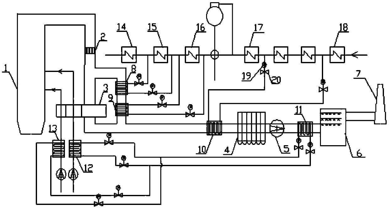
[0038] like figure 1 As shown, this embodiment includes a boiler 1 , a denitration device 2 , an air preheater 3 , an electrostatic precipitator 4 , an induced draft fan 5 , a desulfurization absorption tower 6 and a chimney 7 sequentially connected along the flue at the tail of the boiler 1 . A first bypass is connected in parallel with the air preheater 3. The first bypass is connected to the second high-pressure heater 15 and the third high-pressure heater respectively through the regulating valve 20 and the connecting pipeline through the primary heat exchanger 8 and the secondary heat exchanger 9. The water inlet pipe and the water outlet pipe of the heater 16 are connected to form. Under the condition of high load of the unit, under the condition of poor coal quality, especially when the fuel of inferior quality such as lignite is used, and the amount of flue gas after the fuel is burned is greater than the designed amount of flue gas of air preheate...


PUM


Abstract

The invention relates to a system capable of utilizing smoke waste heat in a gradient mode for assisting in removing SO3 and improving dust removing efficiency. The system comprises a boiler, a denitration device, an air preheater, an electric dust remover, an induced draft fan, a desulfurizing absorption tower, a chimney, low-pressure heaters, high-pressure heaters, heat exchangers, regulating valves and flow pumps, wherein the denitration device, the air preheater, the electric dust remover, the induced draft fan, the desulfurizing absorption tower and the chimney are connected with a flue at the tail of the boiler in sequence; the low-pressure heaters, the high-pressure heaters and the heat exchangers are arranged on bypasses; the regulating valves and the flow pumps are arranged on pipes and used for controlling flow; the air preheater is connected with the first bypass in parallel, the second bypass is arranged between the air preheater and the electric dust remover, and the third bypass is arranged between the induced draft fan and the desulfurizing absorption tower. The system follows the energy gradient utilization principle, smoke of the boiler is divided to three parts for waste heat utilization, and the smoke waste heat is deeply recycled; besides, the specific resistance of dust in the smoke can be changed, the electric dust removing efficiency can be improved, and the SO3 concentration in the smoke can be reduced.

Description

technical field [0001] The invention relates to a waste heat utilization system of flue gas at the tail of a coal-fired power plant, in particular to a step-by-step utilization of waste heat from flue gas for the coordinated removal of SO 3 A system to improve dust removal efficiency. Background technique [0002] At present, some coal-fired units have the problem of high exhaust gas temperature and large exhaust heat loss. The exhaust heat loss is the most important heat loss in the operation of the boiler, generally about 5%-12%, accounting for 60%-70% of the boiler heat loss. The main factor affecting the exhaust heat loss is the exhaust temperature. Under the circumstance, the heat loss of the exhaust gas increases by 0.6%-1% for every 10 ℃ increase in the exhaust gas temperature. In addition, the high exhaust gas temperature will also cause the specific resistance of the fly ash to be too large, resulting in a decrease in the dust removal efficiency of the electrostat...

Claims


Application Information

Patent Timeline
IPC IPC(8): F23J15/02F23J15/06
CPCY02E20/30
Inventor 郑文广宋华伟何胜朱良松刘博李乾坤刘沛奇
Owner HUADIAN ELECTRIC POWER SCI INST CO LTD
Why Eureka
Try Eureka